
“This project was originally started as part of the i3 Detroit OpenAccess control system for RFID entry. I promise I’ll write an entry on that soon, but I’ve got to shake down all the bugs first.” That was two and a half years ago. I’m going to do a write up of all the aspects of the system I designed even though I have no intention in actually implementing this system. The reasons I have for not using it are basically: I won’t be the only person responsible for repairs/debugging, I won’t implement any more features I don’t think are useful, no one has stepped up to learn about it. The system it’s replacing is an off-the-shelf rfid mag-lock with keypad and while that is lacking a lot of features that would be helpful I am not moved to change anything because the benefit of features vs. the cost on my time is not worth it.
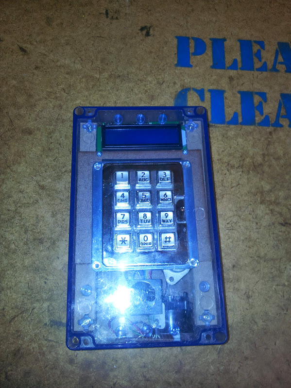
The first aspect of this system is the front panel controller. My re-implementation of the OpenAccess system had to start with adding the ability to enter PINs. Now, there are plenty of other systems that hackerspaces use or have built but a minority of them use PINs, it just seems that they either choose a more interesting method of second factor in their identification or forgo it entirely as being un-needed. Considering the physical part of the security is usually the weakest link in the system most people have decided that the brick next to the window makes a PIN to go along with the key sorta pointless.

old schematic, not using i2c for the final design (and am setting contrast locally)
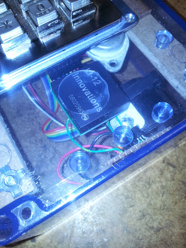
Since I rewrote everything from the ground up I got to choose a control panel for the outside. Originally I wanted to use the rs485 control panels but talking to them ended up being cumbersome and the more I used them the more I hated rs485 (at least use rs422, it’s full duplex). This control box has 12 volt power, ground, wiegand signals for the rfid reader (the buffered inputs are on the OpenAccess main board) a single ds1822 temperature sensor, rx and tx pins to the atmega I’m using, and (according to my schematic) the contrast pin for the lcd. I can see from my code for driving this display that I am controlling the contrast locally (actually, for outdoor use a VFD would be much better in michigan winters and as everyone knows is sunlight visible). I am not reading the temperature locally, although I have the spare pins to do that. You can see for the RFID reader I put an orange LED and a western electric warble buzzer on the output pin of the rfid reader.

Old processor

Adapter!
This code started out as an i2c display and keypad that used an attiny. I thought that if I used someone else’s code I could avoid having to debug it. WRONG! Let’s start with this: if you ever try to use i2c over a cable, just don’t. Inter-integrated circuit communication should be done on a single board. If you have to go off board use SPI or UART. My experience with that i2c controller wasn’t great. I think I might have been running up against memory restrictions on the attiny2313, but considering a pro mini from china is about as cheap as sourcing a single attiny chip here…. I replaced it. My code for the display uses serial, good old fashioned reliable serial that takes no special tools to debug or talk to.
The code I have works like this:
- read for serial commands and do any of them
- if a key was pressed, return it over serial (no line breaks)
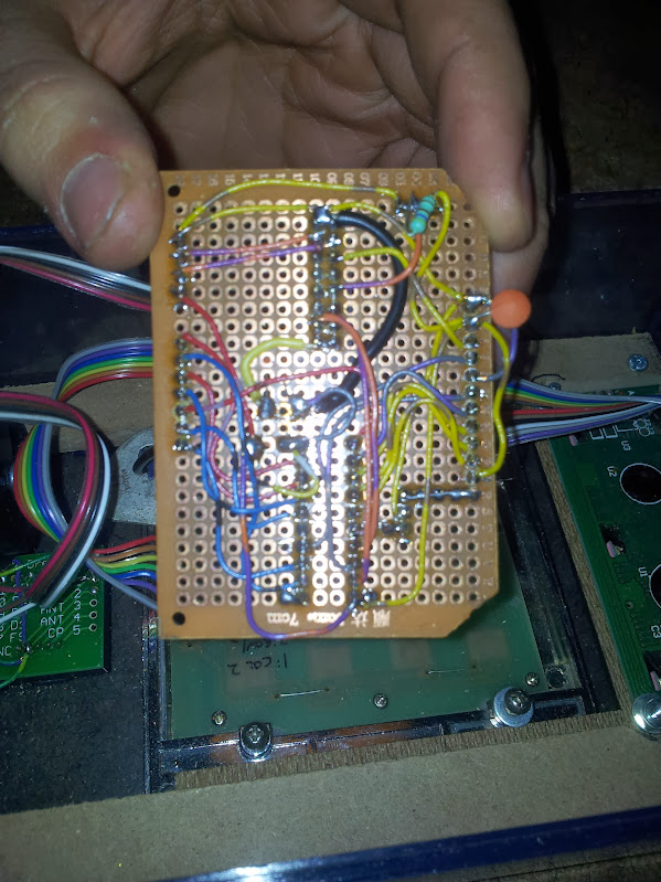
That’s it. The commands are for brightness, contrast, display, and display line. The display command works from the last cursor position and the display line command rewrites the whole line. That is exactly how simple this code is. The contrast and brightness are done with PWM from the arduino pro mini, I use a keypad library and serial command library (specifically modified for the 328 as opposed to the 2560 which I will cover in a later post). I fully support the modularization of your software, this extends to the modularization of your hardware. I could run a thicker cable and have all the keypad and lcd pins run back to the main microcontroller, I could even use local chips to multiplex those pins, but having a second brain at the other end able to take human-readable commands just made it so much easier.

New processor
Code is here.
Pictures and schematics are here.

June 30, 2016 at 3:24 pm |
[…] Hacks, repairs, arcade games, sci-fi, and some very bad ideas with possibly humorous consequences « Arduino keypad and display […]
July 1, 2016 at 1:22 am |
[…] on the uart lcd and this one on the arduino mega. The front panel controller was discussed in a previous article, the last one is what we’re here to […]
July 1, 2016 at 1:33 am |
[…] be able to set the contrast of the LCD based on it, I didn’t know how to put the logic in the uart lcd so I made it externally controllable with the thought to add logic later. The function to check […]