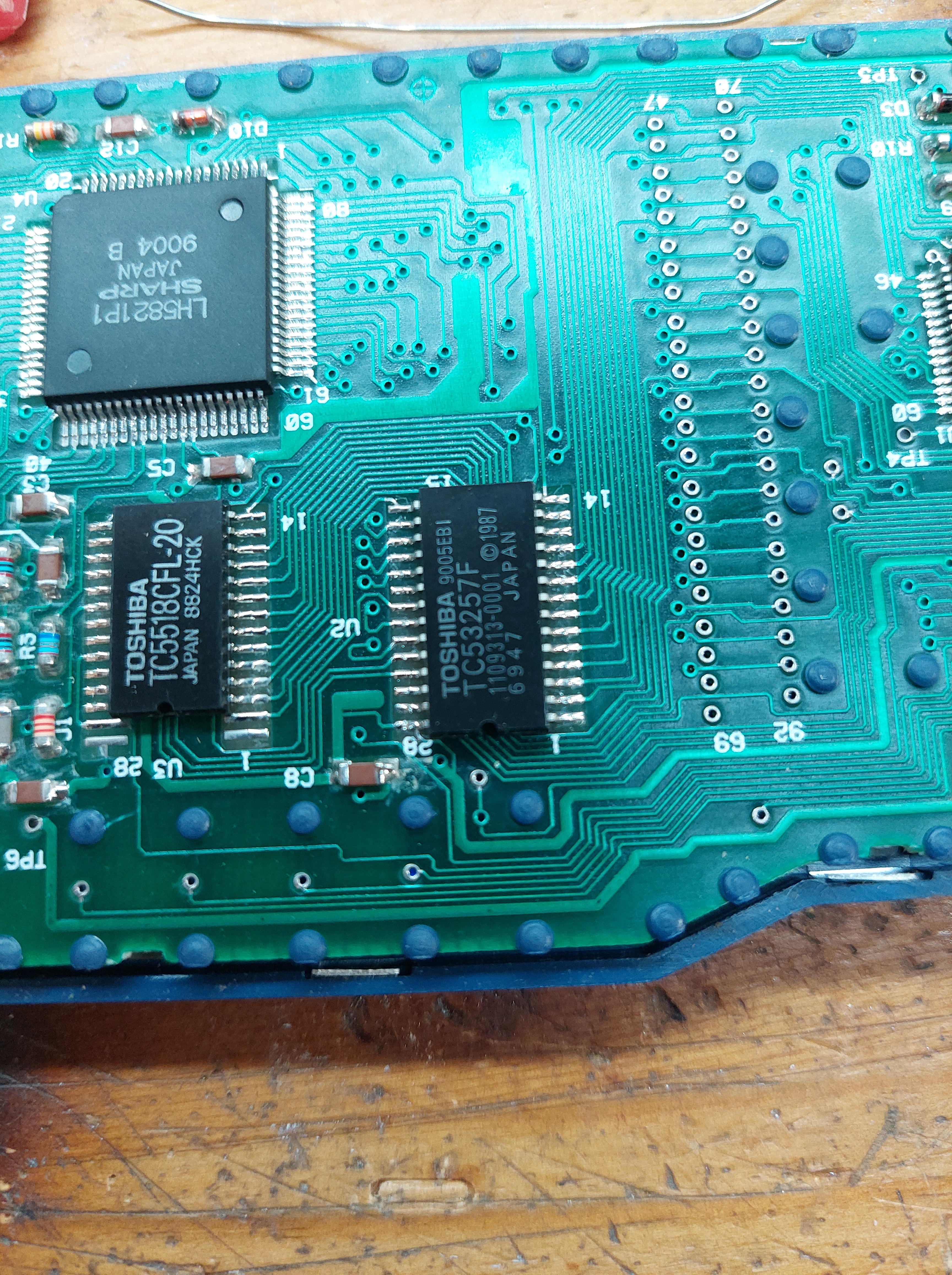
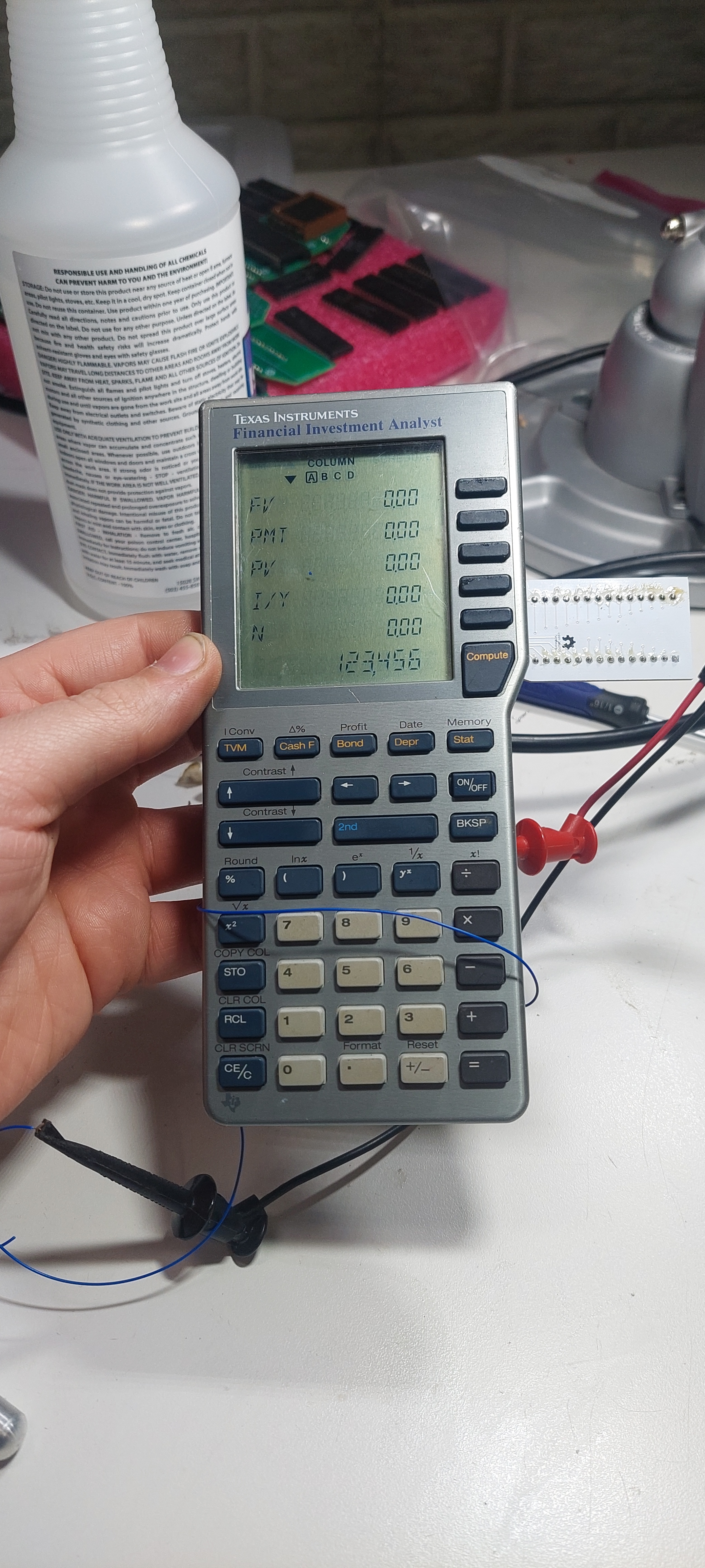
This is a somewhat generic idea, but I’ve implemented it for a specific purpose. In trying to be able to dump all the TMS7000 series processors’ internal mask rom I’ve come across some pretty unique ones. The latest ones are the TMS70C46 processors found in the TI-74 basicalc and the FIA-10 financial calculator. These calculators seem to contain internal mask rom, but they also have built in address decoding to select different memory chips for different regions of memory.
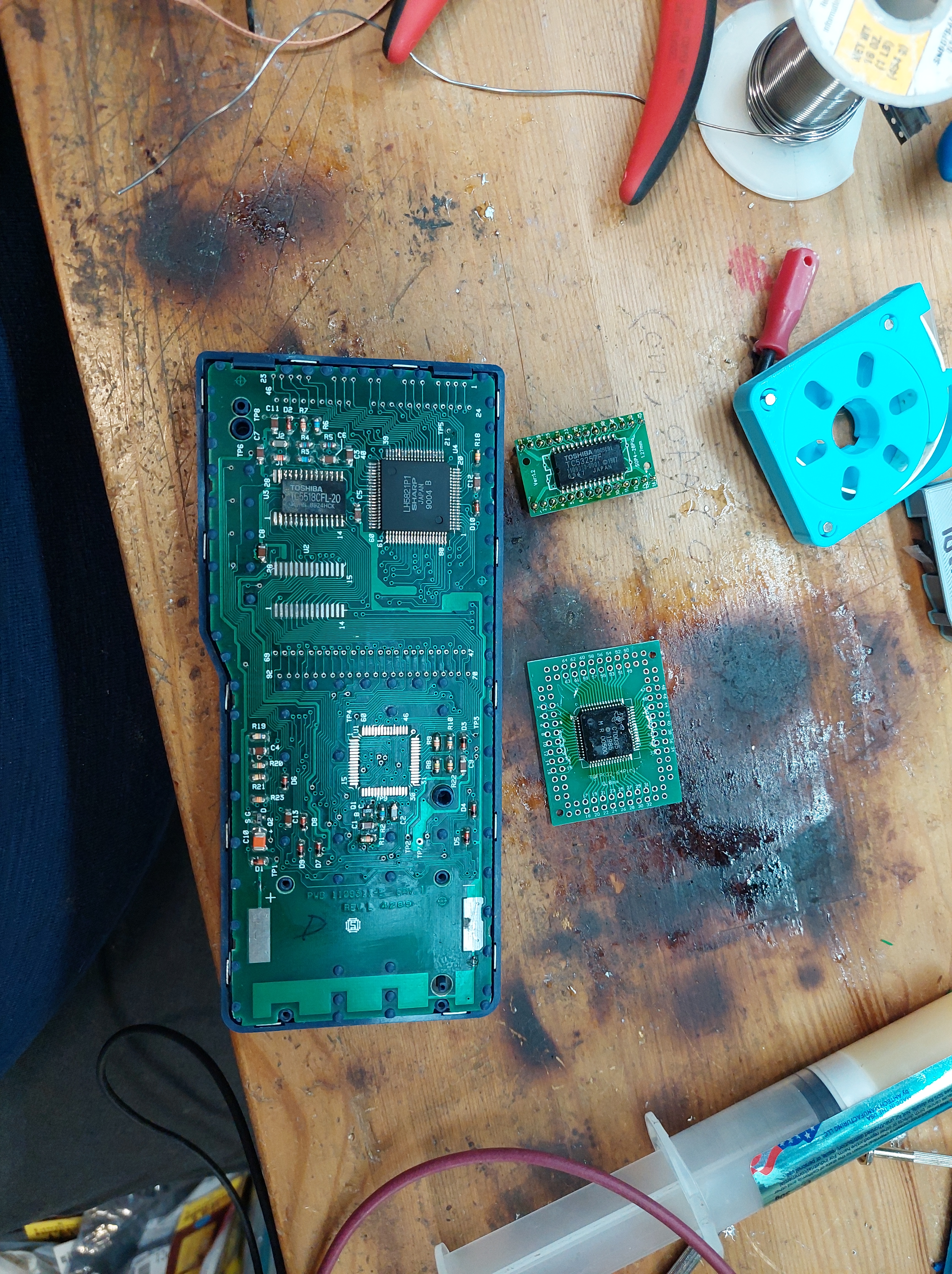
This makes it more difficult to capture any of the reads to external memory because now we need to know which region it’s trying to read. I attempted to diode-or these together and use the standard dumper we have been using, but that didn’t work and it’s hard to know why. I am fairly confident that for the FIA-10 I know where it either executes all of its code from, or where it gets at least some from: the external mask rom.
I have already desoldered this ROM to read the contents, but now I want to put my own code there. Not just code, it would be very convenient to actually talk to the processor and command reads and writes to different regions to see what happens. I have a way to do this, it’s called Demon Debugger. There isn’t a target for the tms7k yet, but that part shouldn’t be too hard. What I need now is a way to get our code into the processor. Our latest version of Demon Debugger fits where a standard 2716 would go and uses certain regions for input and output so we could just replace the external mask rom if we know what area it’s trying to read. But how do I cable that in to this SOIC chip?
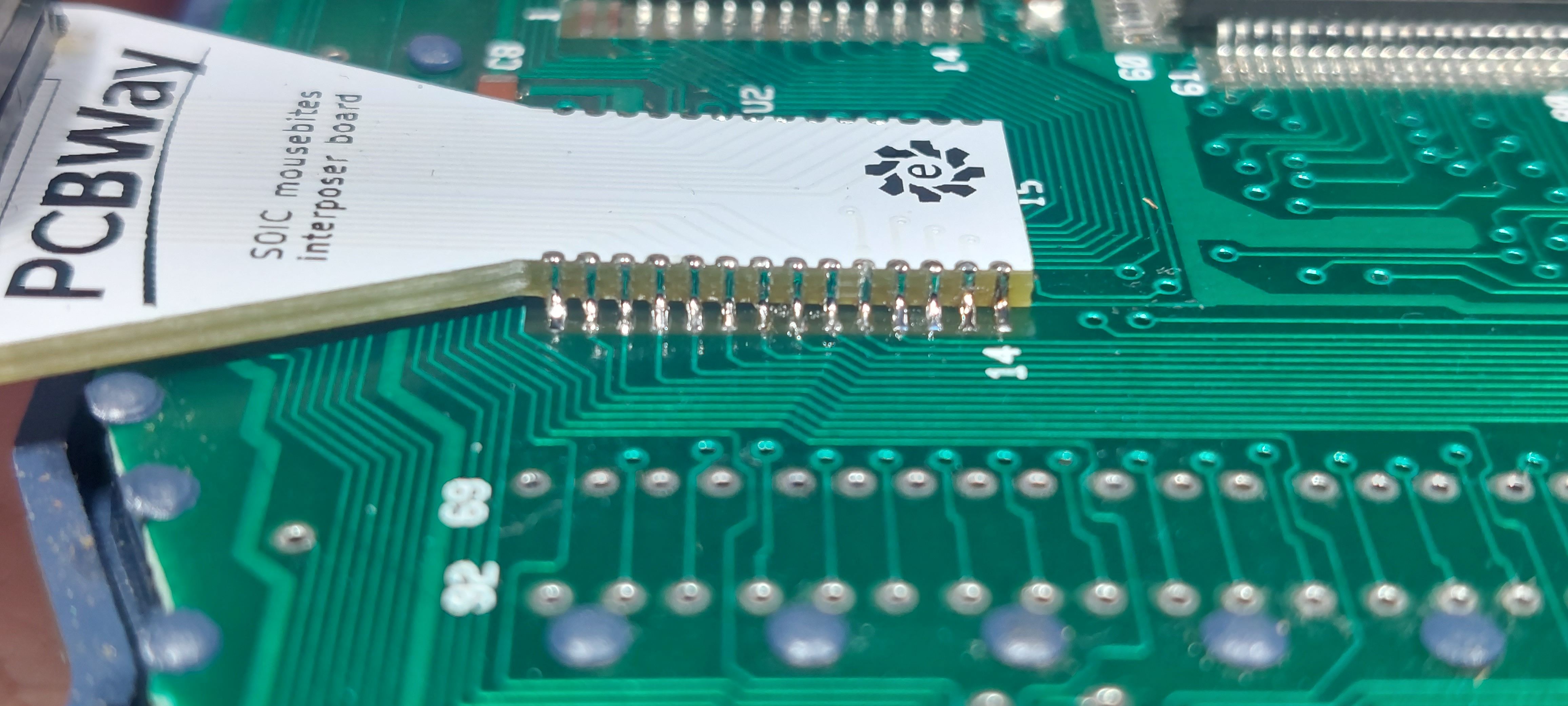
This is the latest board I got sponsored by PCBWay. This is what I’m calling the ‘mousebites’ adapter. That’s the term I’ve seen for castelated pins on the side of a board, and I think it’s cute. I used the datasheet for the exact mask rom that was installed there to get all the measurements needed to line up my board so it can be soldered where the rom chip used to be.
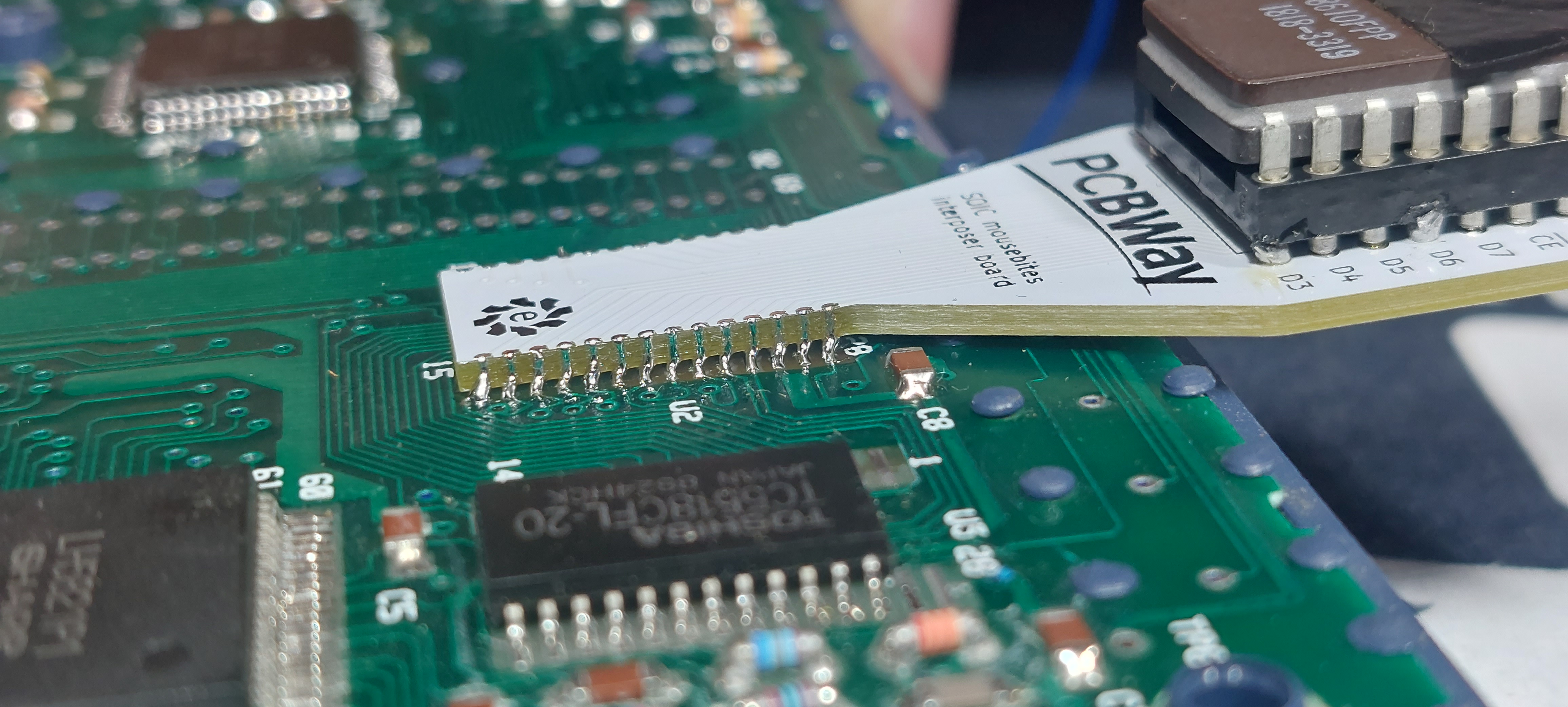
After installing this I realized it would be a perfect use case for a flexible PCB, but I didn’t notice the plastic bumps securing the board before I got this installed. That being said I got this one made in white with black silkscreen and that looks very sharp. I can tell why most boards tend to be green, because I can’t see the traces on the board as well with the white. The silkscreen on the soldermask though, that’s very distinct with this color combination. If you’re going to enter PCBWay’s 10th aniversary contest, this could be a good choice for your design. That is if you don’t want to venture into their full color printing.

This is what it looks like with a standard rom in the socket that I intend to use for demon debugger. It’s fairly rigid, but with all that leverage I’m afraid it’s going to rip traces right off the board. In order to prove it works as-is I put the same data from the mask rom on a standard 27256 to see if it’ll boot.
And it does! This sort of adapter has many uses, but unfortunately the orientation is pretty specific. I designed this one to stick out the edge of the calculator. If the orientation were flopped it would not work at all. If I made this as a flex pcb it would be more generic, but even then it’s not a sure thing. As it is this one works and I’ll be interested to see how It works with demon debugger.

May 6, 2024 at 11:27 am |
[…] See the entire process and more about the PCB in the post here. […]