This is unusual for me, but I want to get it out of the way first. This project was sponsored by PCBWay (every time I read that name I can’t help but hear it the way Retro Recipes says it on youtube). I’m happy they wanted to sponsor some of my projects, I see them all the time on youtube, but my methods of documentation are more text and image based as opposed to shooting and editing video. They have a lot of different manufacturing techniques in-house and I hope to sample all of them because I am already considering uses I have for sheet metal bending and flex PCBs. I’d already designed this board when they approached me about a sponsorship and despite being able to get the same part milled or printed, I went with my original plan of making it out of circuit boards.
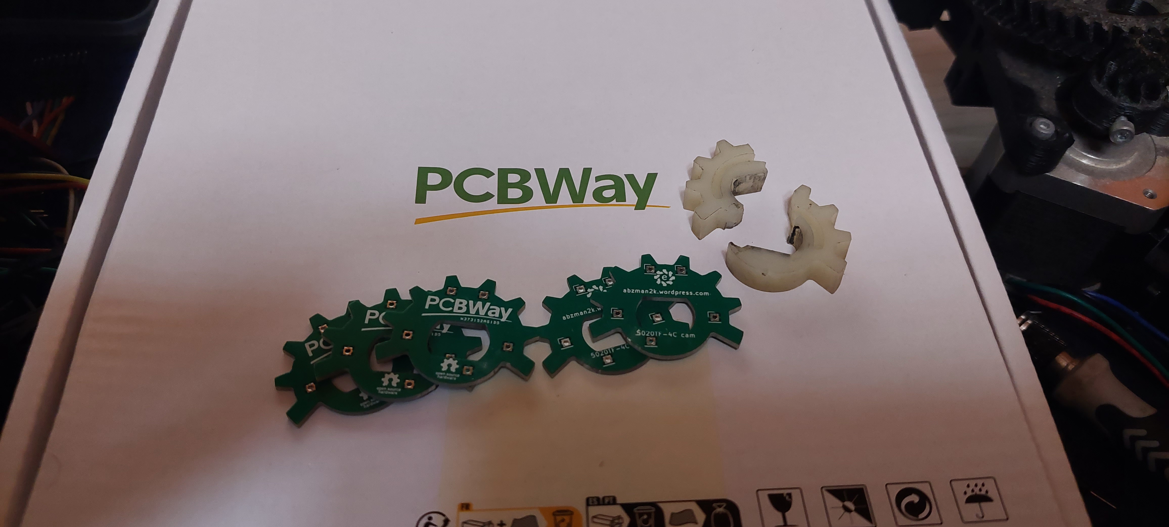
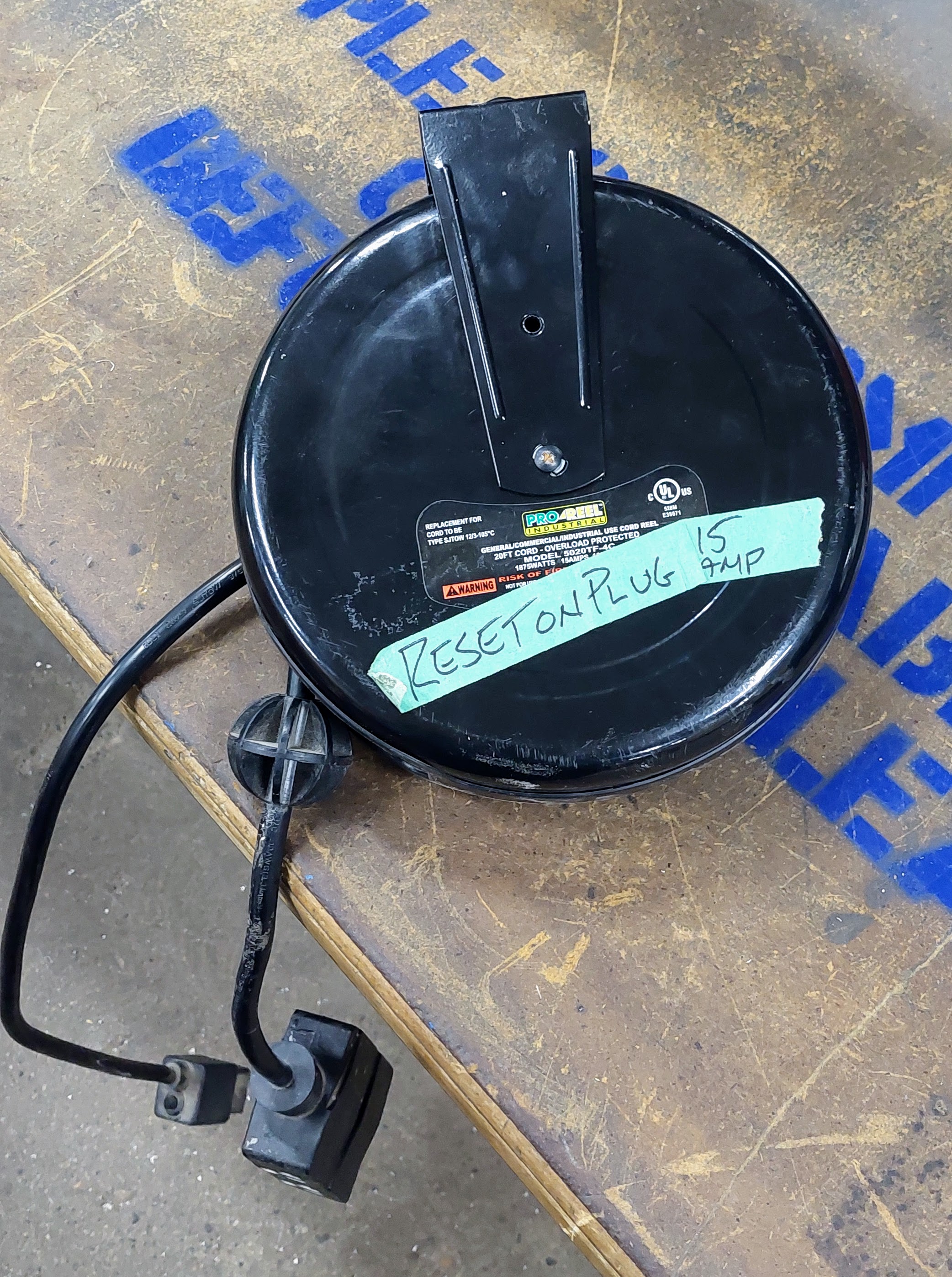
What, you may ask? Well it’s the part you see above. This is the detent cam out of a retractable cord reel. Specifically a 5020TF-4C good for 15 amps with built in circuit breaker and WOW, it’s over $130 still. That’s a good enough reason to attempt a fix.
This part is only 34mm across and with how it sheared gluing it back together didn’t work. It’s possible that we could have epoxied it back to the shaft or tried to drill through it and pin it, but making a new one didn’t seem so daunting. The trouble is, with the thin part of the tooth only 2mm across I am not confident a 3d printed part would hold up, especially my home FDM printed stuff. The fun part about this though is it’s only 2.5D, meaning it has features in 2 dimensions and has thickness but nothing else of note in the third dimension. I thought about milling one out of aluminum, but I’ve been making PCBs for over a year now non-stop and fiberglass and copper sounded plenty strong enough for this part. I’m pretty good at using KiCAD, and that’s basically the only CAD I’m good at using so I might as well solve my mechanical problems the way I solve my electrical problems, making a circuit board. I’m working on getting back into Solidworks, but I have plenty of low hanging fruit to work on in the circuit board world right now. The only thing really interesting about it is the design and assembly process so I’ll detail that here.
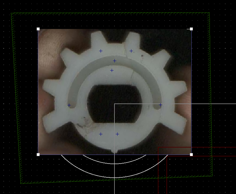
I held the part together and scanned it on my flatbed scanner. I use NAPS2 (Not Another PDF Scanner 2) to do all my scanning and light editing before saving. I can rotate the images to get them lined up exactly square then save them as tiff and retain a 1:1 dimensional reference. This actually prompted me to install KiCAD 7 which added the feature you see above where you can add images on layers so you can trace them. For ease of reference I set my coordinates centered at 0,0 and laid out my guide lines from there. Everything I measured I referenced with calipers where possible, but in reality I just traced it most of the way. The part is small, but not precise in how it’s used.
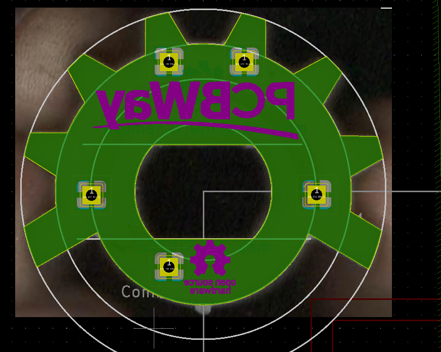
Once I traced it out it was just a matter of throwing some through holes for fixturing the layers together and adding copper planes for rigidity. This is a mechanical design, not an electrical one so you’ve got different considerations. I didn’t really think through assembly, but it went OK.
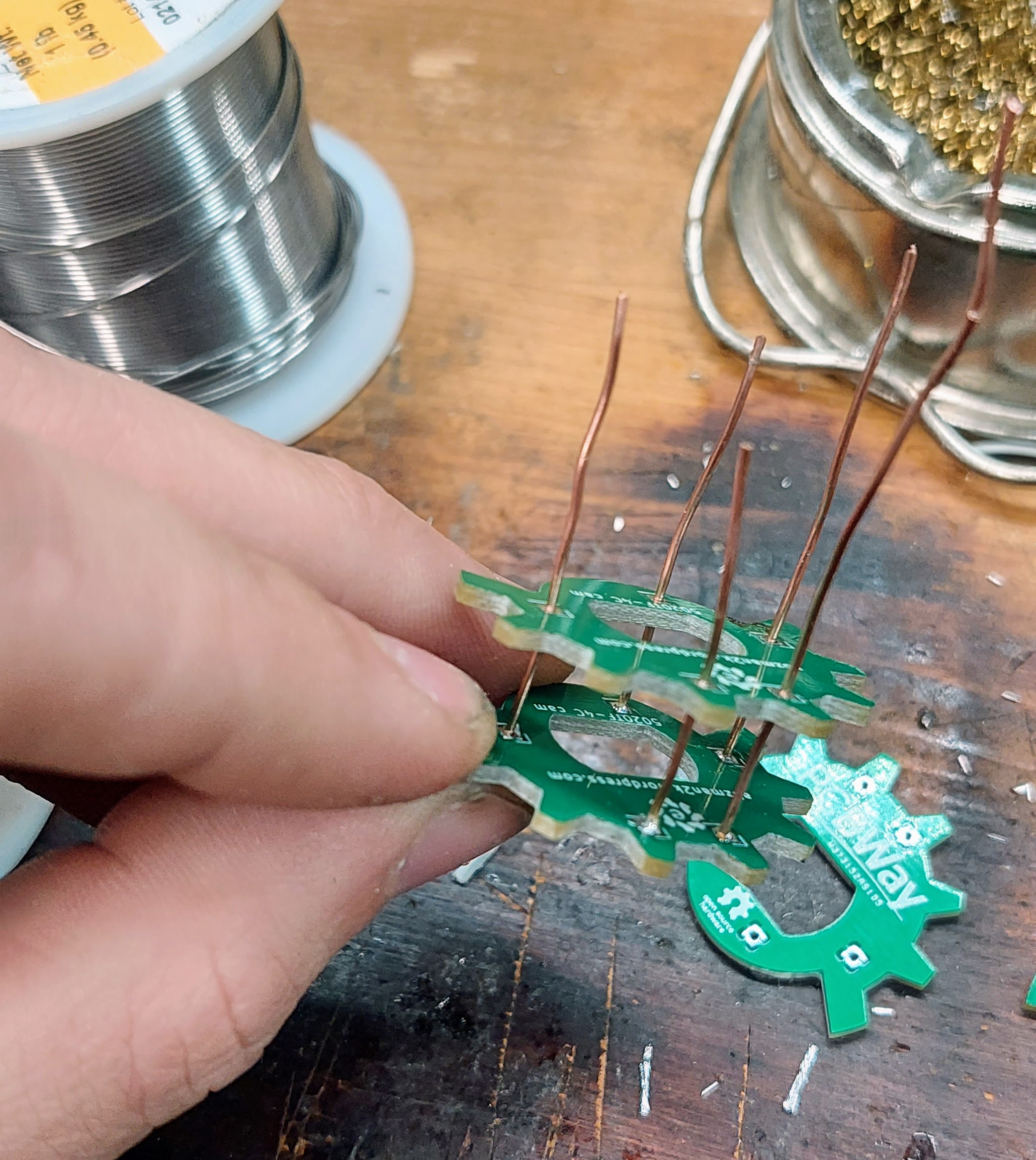
I chose some solid core wire and soldered them to one of the layers, don’t worry if there’s a blob and the next layer can’t sit flat. It’s helpful to have each wire a different length so you aren’t trying to line up more than one at a time. Then add the next layer as far down as it can go and get it soldered as well, make sure the joints are good and it is fully wetted. Keep going until they’re all installed and you have a slightly lopsided looking layer-cake. Once you have that all installed get out your trusty heat source and blast away.
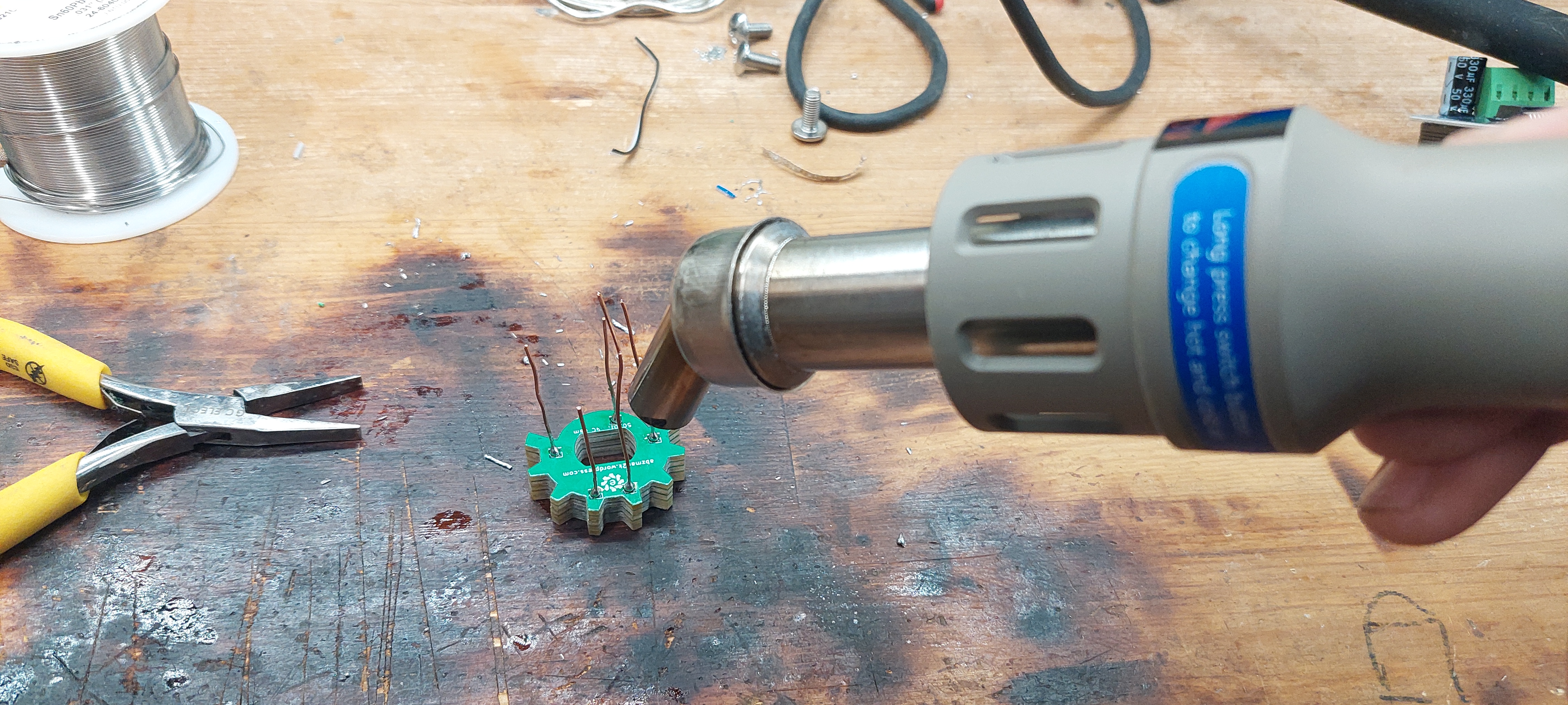
I have a hot air reflow station, but you can use a propane torch, or mapp, or whatever. I suggest something that’s not an oven so you can manipulate it while it’s heating. Once everything’s molten you can press down and get everything flat. This is the time to grab one of the wires with some pliers and manipulate it so it sits straight up and is not stacked at an angle. If you’re impatient like me now is the time to douse it under running water to cool it down so you can touch it.
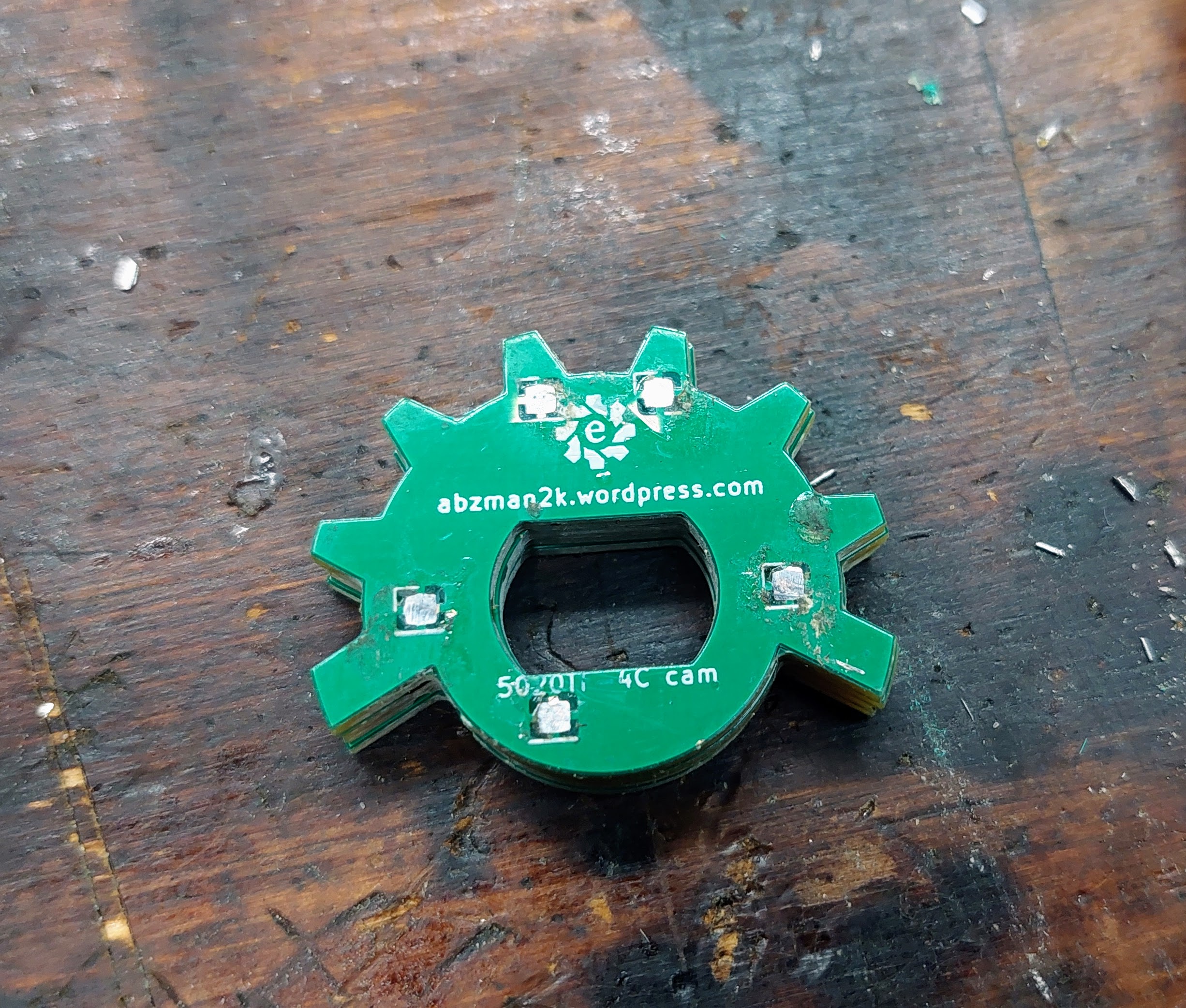
Once it’s cool take a box cutter or other sharp blade and whittle down the soft lead, tin, and copper until the surfaces are smooth and there’s no solder bump on either side.
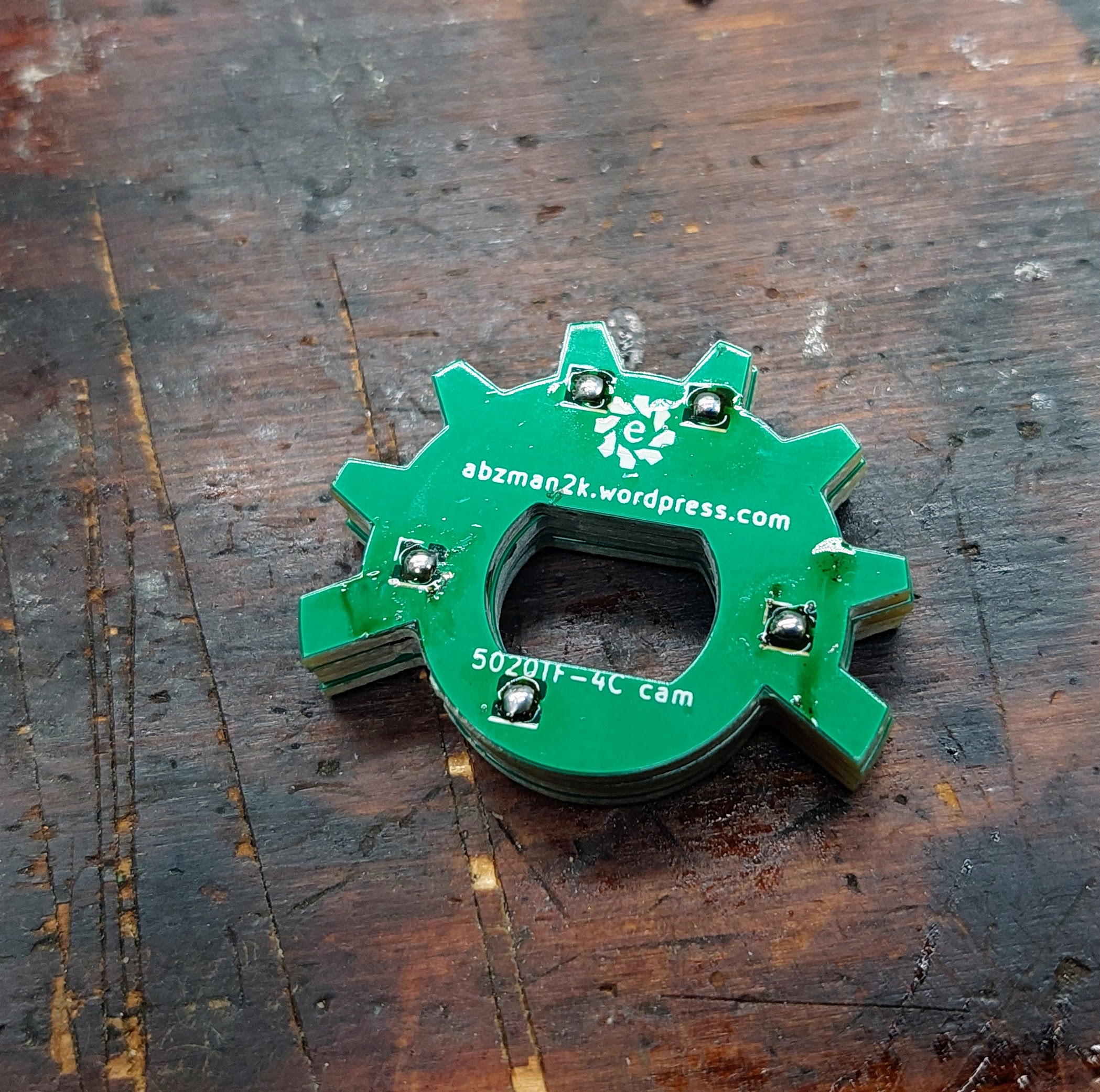
I originally did this with 4 of the 5 boards all the way to this point, then I checked and found out the original part is closer to 5 boards thick so I used the heat gun to separate them all and do it again with all 5. Don’t be like me, check first. With all this work, will it fit?
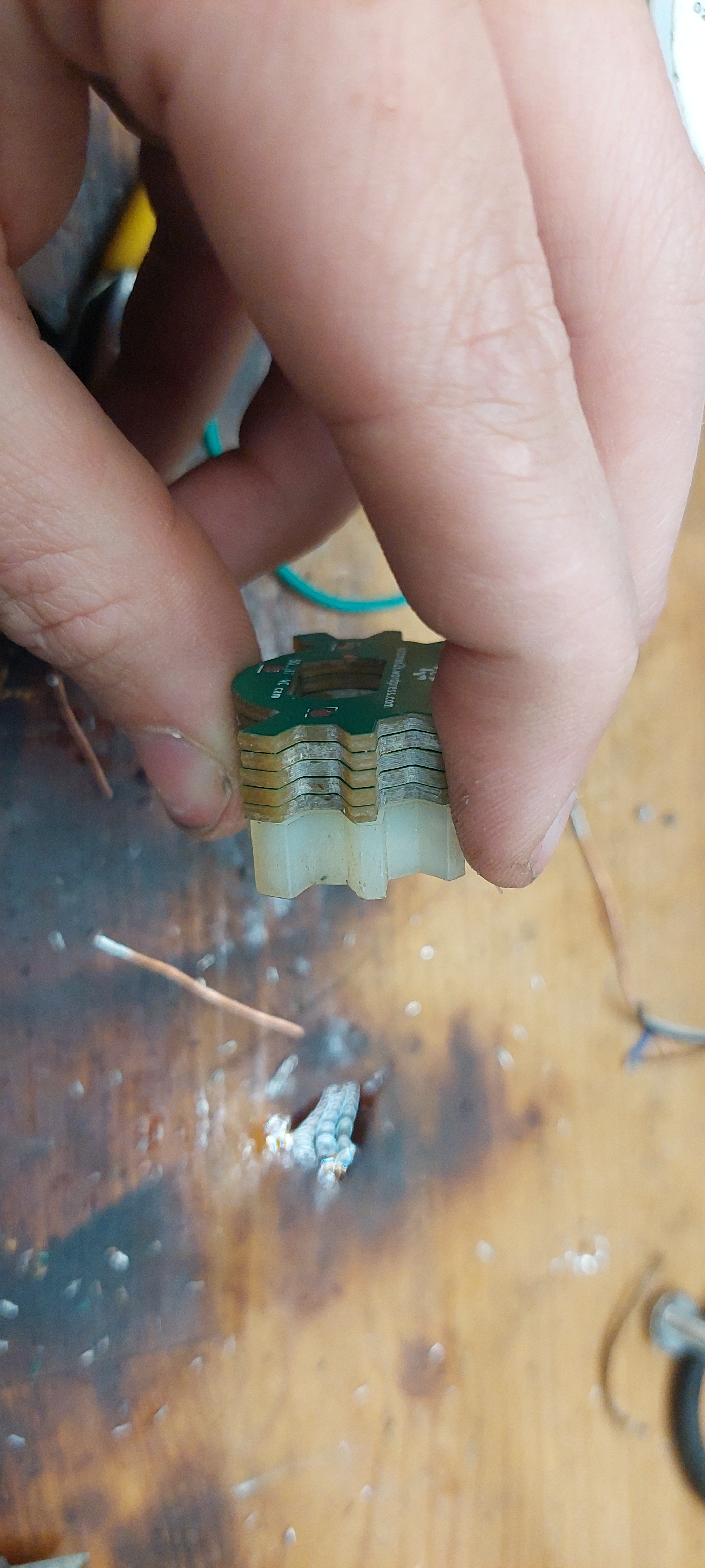
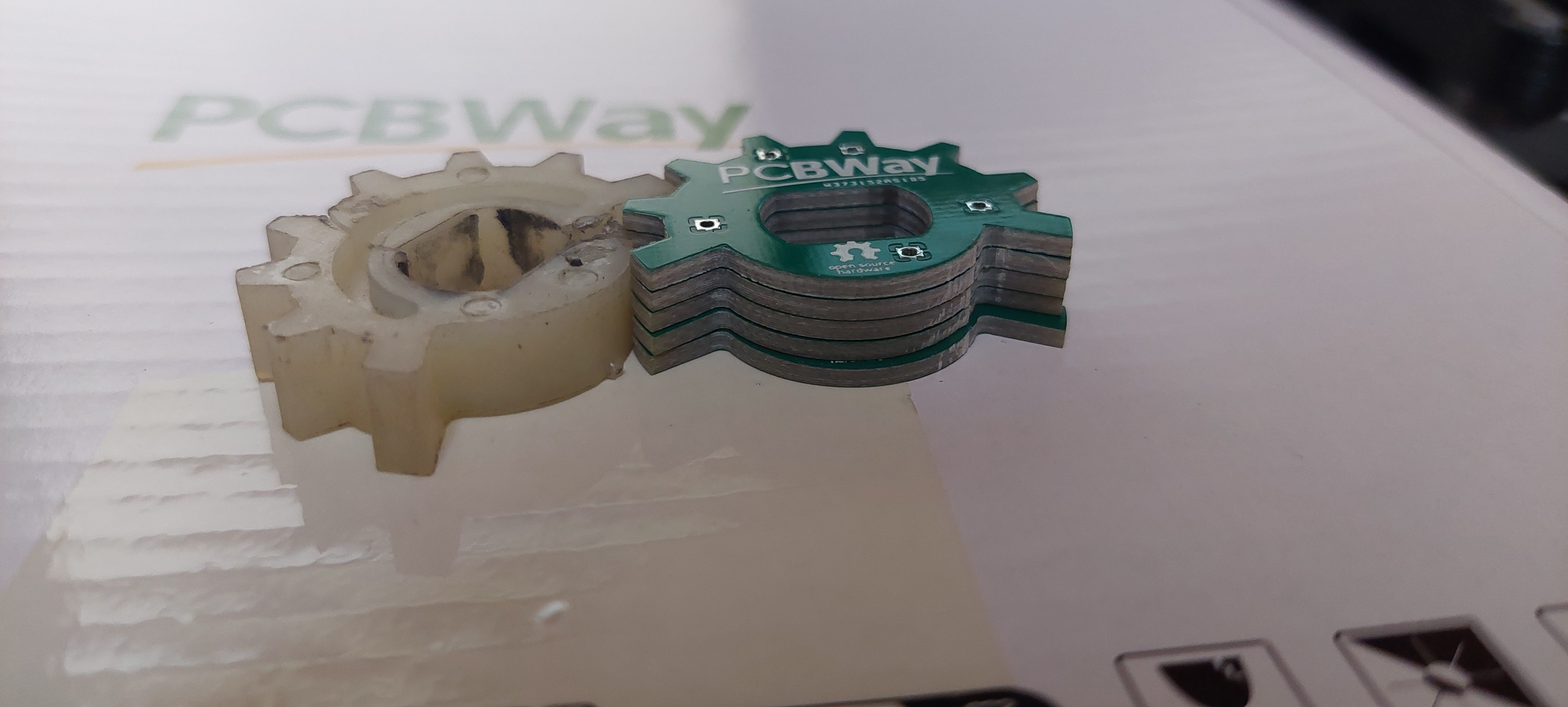
It certainly looks like it. I didn’t do a perfect job stacking the boards, if this is a critical part then you might opt for a tall jig to hold them all perfectly stacked while the solder cools, but for this project close is fine.
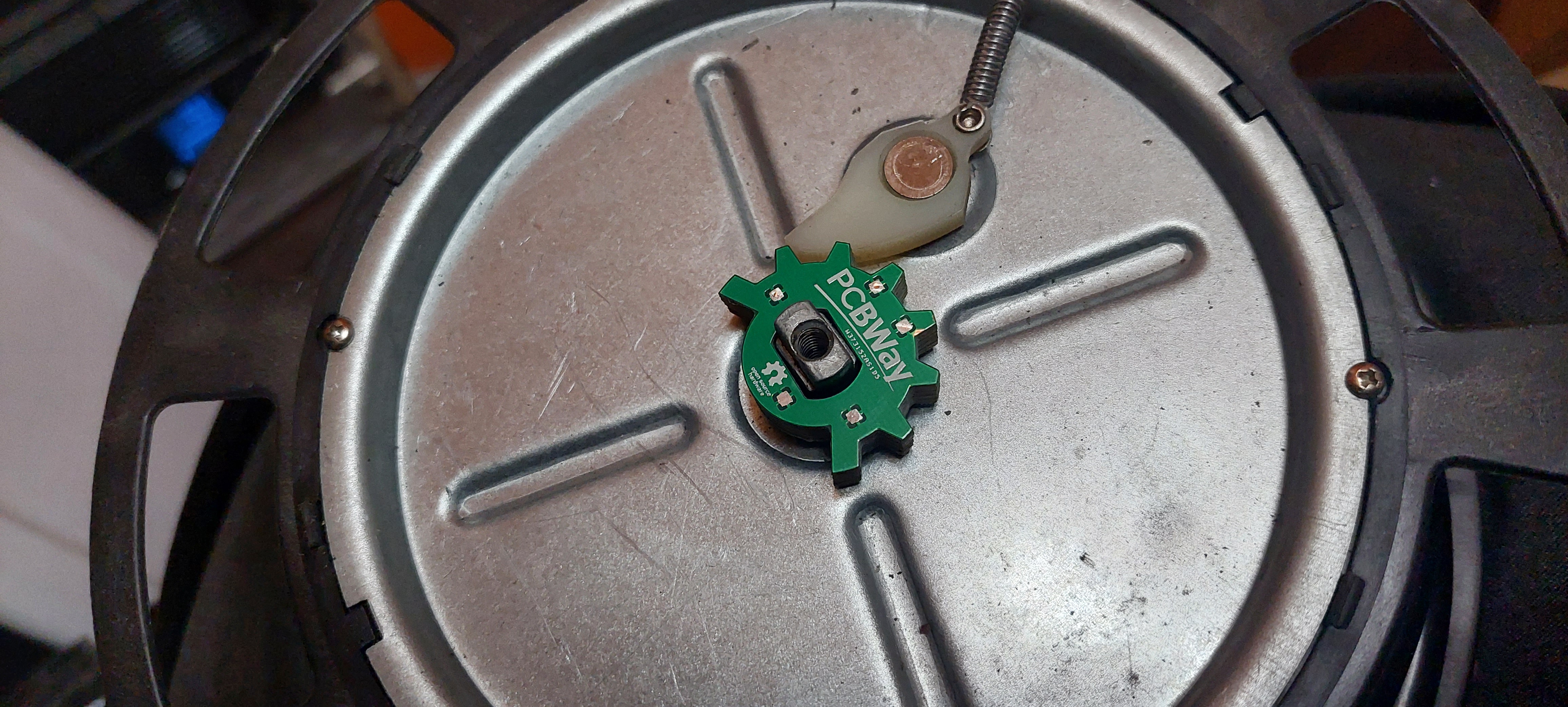
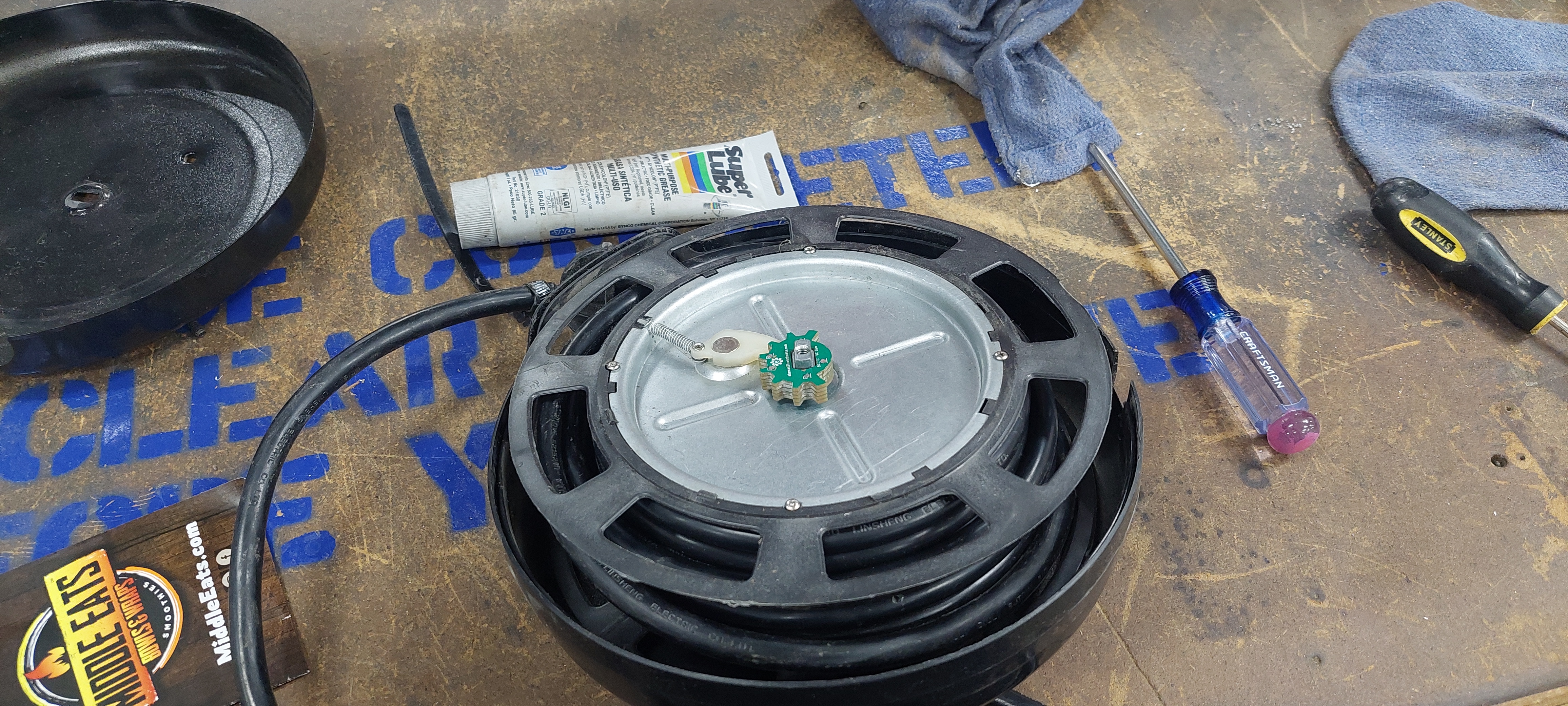
There it is, it fits great and is just the right thickness. Putting this cord reel back together is a bit of a chore. I thought about pre-tensioning the retraction spring, but if it’s hung from the ceiling then whatever height the cord sits at normally would constitute the pre-tensioned amount.
A word of caution when assembling this. The detent can be installed either way, it’s symmetrical, and you might think that doesn’t matter, but being 180* off actually can cause a problem. When the cord is fully reeled out, meaning the operator has pulled it all the way out and the place where the cord is lined up with the exit hole of the reel, the cam has to be in the retract position. If it’s engaged in a tooth, then no matter how hard you pull on the cord the reel won’t turn any more and the cord is stuck all the way out. I had to reach in and push the reel around until it was back off the teeth until it retracted. Once I flipped the cam over that problem went away because even though it’s symmetrical, the place where the wire meets the reel needs to be aligned relative to that cam or it can get stuck.
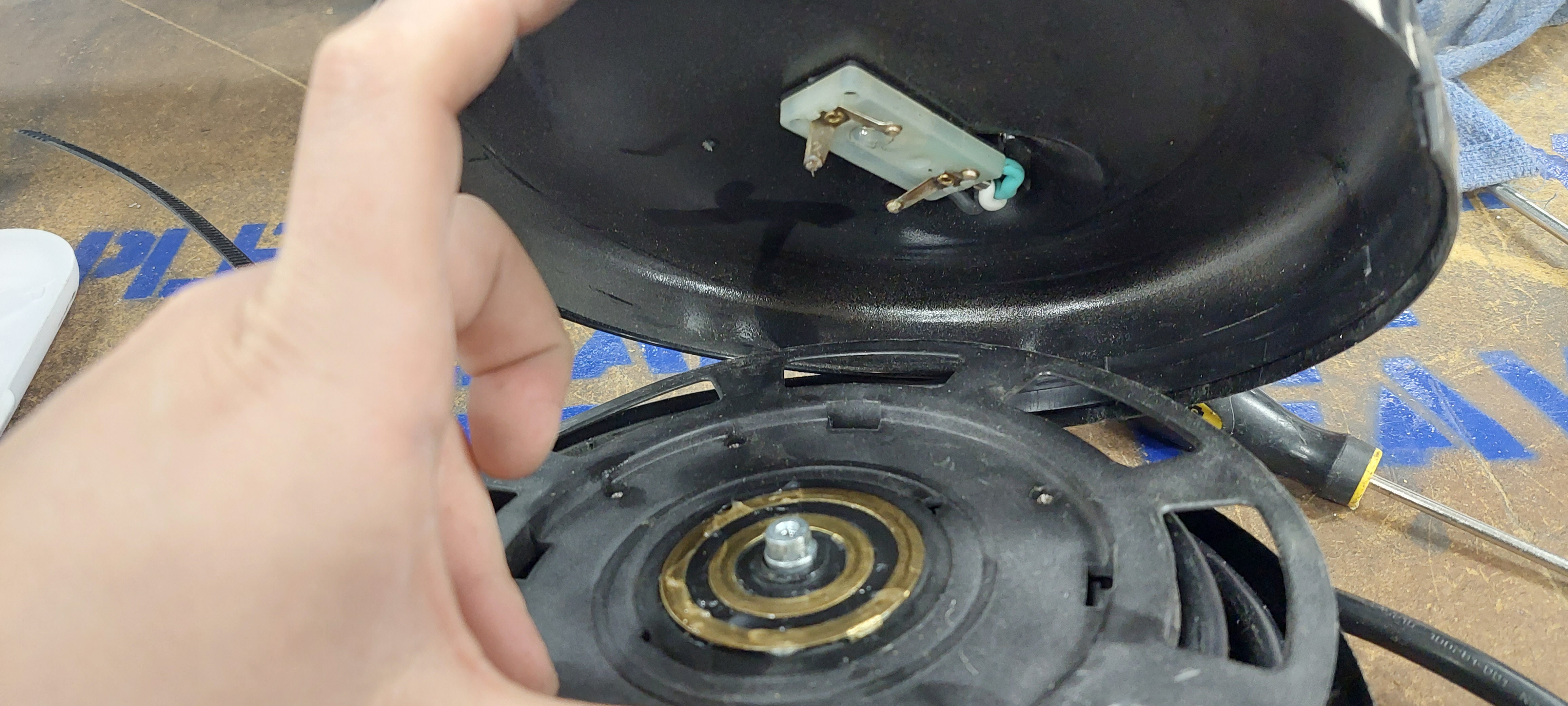
I also recommend while you’re in here lubing up the slip rings with some dielectric grease. You wouldn’t want pitting or corrosion on those surfaces, they pass all 15 amps of current you know.
There it is, all back together. It works great and now anyone with the same issue can save themselves over $100 and keep these parts out of the landfill. I have this project hosted on my github if you need the editable KiCAD files here. You can export that board as a 3d model and extrude it up as far as you need for other manufacturing methods. I have also uploaded the gerbers to PCBWay here so you can order the parts straight from them. You could try out their 3d printing service or machining but honestly, if you have soldering supplies I think the best price to performance is gotten from the fiberglass and copper PCBs, they’re very strong. I ended up using all 5 of the boards from the minimum order quantity so there’s not even any leftover parts, it works out perfectly. I will be trying out their other services in the future, while I could make enclosures for my S100 computers out of PCB soldered together (I’m reminded of the front panel to Veronica), I’d rather try bent sheet metal.

July 24, 2023 at 1:14 pm |
[…] You know the old saying. When all you have open is KiCad, everything looks like a PCB. That was certainly true for [Evan], who needed to replace a 2.5D small part recently and turned to PCBs to get the job done. […]
July 24, 2023 at 1:49 pm |
[…] You know the old saying. When all you have open is KiCad, everything looks like a PCB. That was certainly true for [Evan], who needed to replace a 2.5D small part recently and turned to PCBs to get the job done. […]
July 24, 2023 at 6:16 pm |
[…] You know the old saying. When all you have open is KiCad, everything looks like a PCB. That was certainly true for [Evan], who needed to replace a 2.5D small part recently and turned to PCBs to get the job done. […]