I’ve taken a liking to this small, simple speaker and when I went to go recommend it to someone as a diagnostics tool I found that you can’t get it anymore. Not retail anyway. This is my attempt to make a work-alike version and maybe eventually it will get cleaned up into a version that can be ‘mass’ produced for anyone that wants one. I don’t have this up on PCBWay to order mostly because I designed it around parts in my junk drawer, but I will send you one if you want. I consider this an actually useful bit of test equipment. If you want to know what sound a device you’re fixing is trying to make, this works quickly. If you’re trying to diagnose an audio circuit like an amplifier you can use this like an oscilloscope and follow the signal through the device by listening. You just have to take a headphone cable, split one end, and poke the circuit with the input signal end while grounding the ground pin, and you can follow the signal until it foes away and then you may have the problem component. I found bad slide pots this way in a mixing deck once.
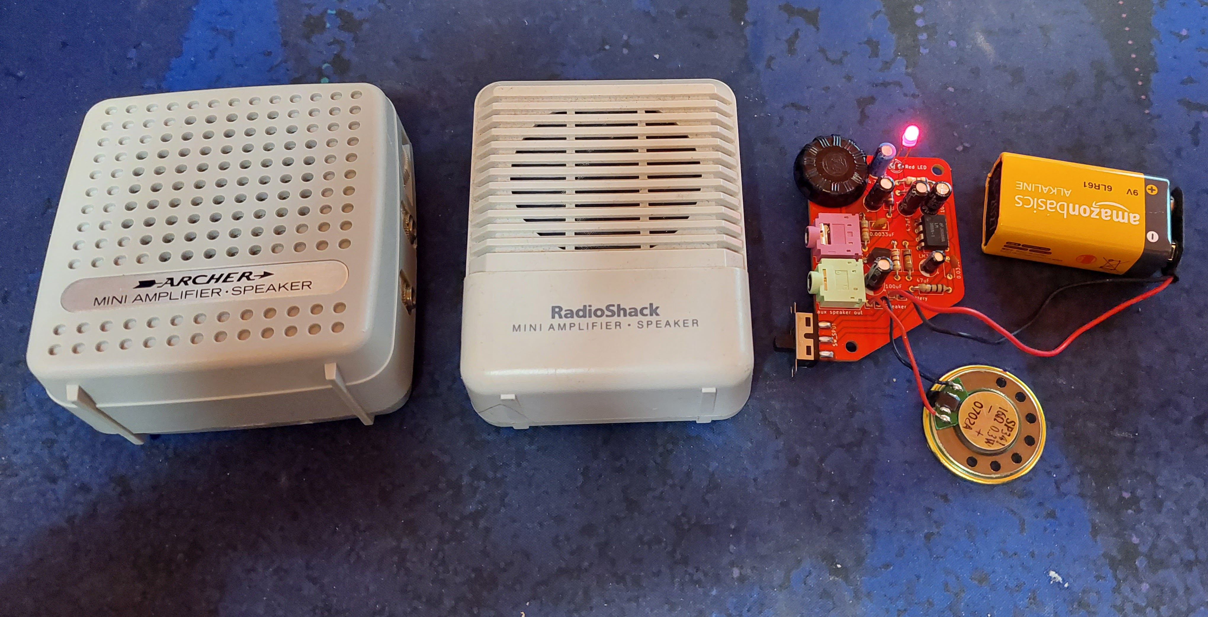
On the left you can see the Archer 277-1008B speaker, in the middle the more modern Radio shack version, and then there’s mine. The original one snaps together and I cribbed my schematic almost entirely from that one, but I made my own changes to fit the parts I had and the features I wish the original had. The Radio shack one has one screw holding it together and a barrel jack for external power if you want. It also has a note calling out that it is center positive as a previous version was not (bad move, but good for fixing it). Mine has a number of alterations and I think it is somewhat improved.

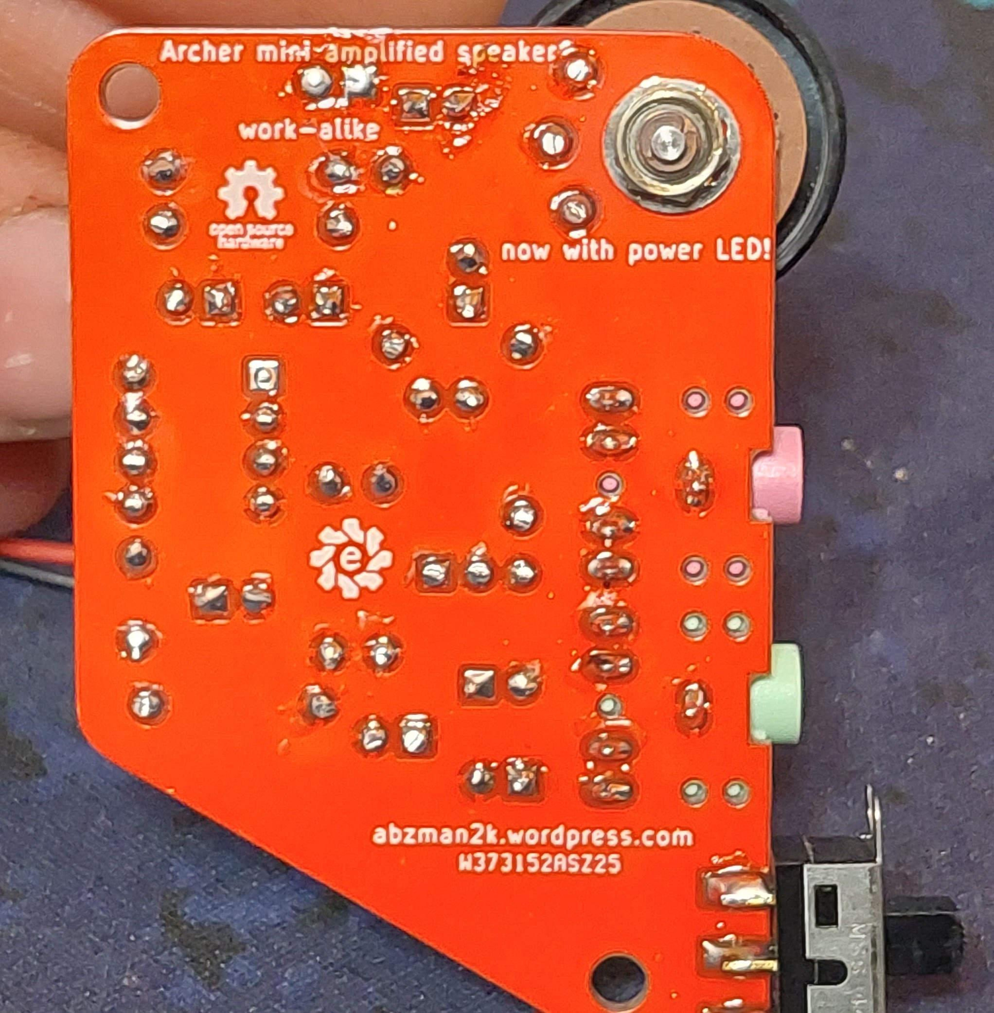
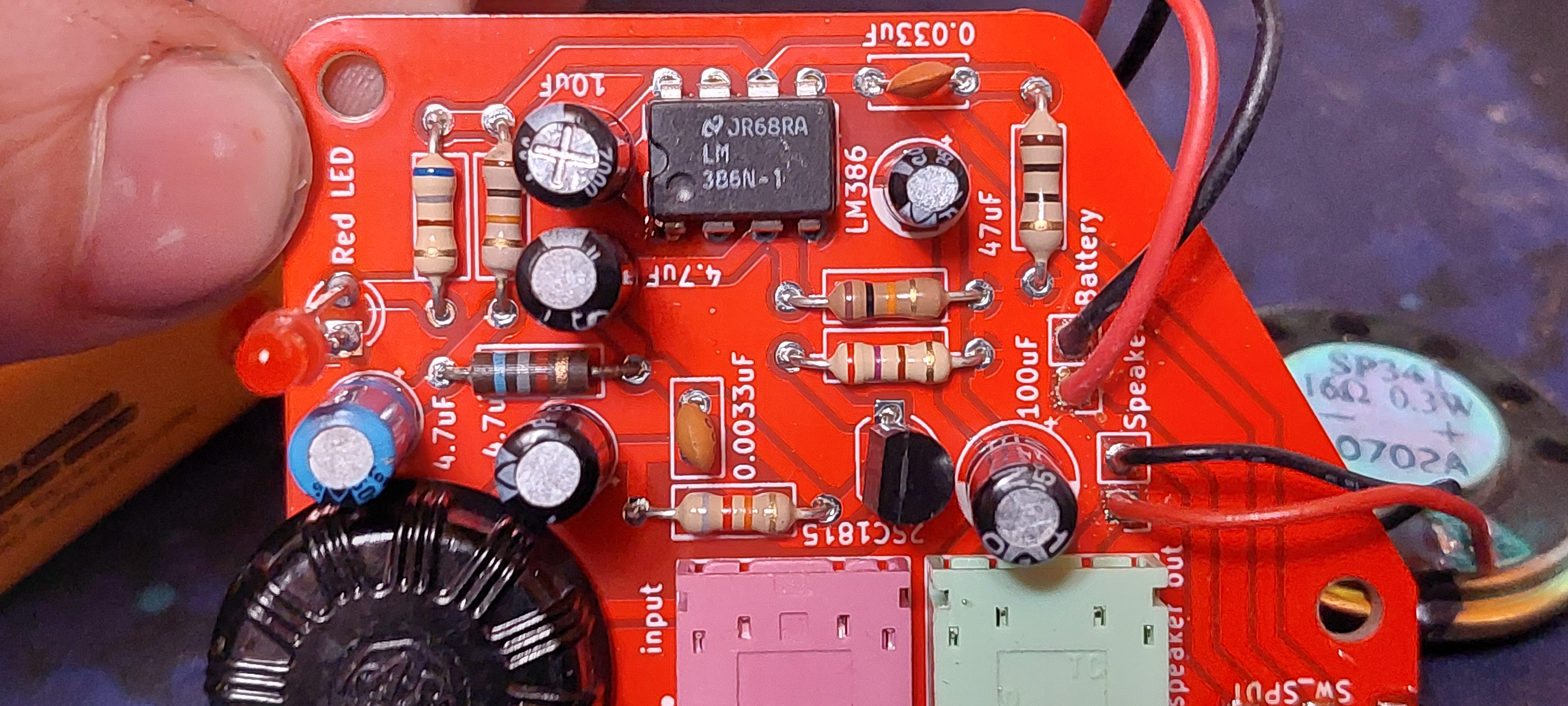
As for the schematic I did a couple things. First I added a power indicator, these speakers will kill batteries if left on and there’s just no way to know if it’s on without twiddling the knob and listening for the crackle. Second I added a switch, the volume pots I had didn’t have a built in switch and I found some switches in a bin that I could use up on this project. The volume pot is actually something I designed a footprint for specifically because I have a ton of them and they’re all identical and I wanted an excuse to use them on something. They’re Allen Bradley parts salvaged by an old Ham that I knew at a previous job. The last thing I did was to use the audio pass-through on the output jack so that when you plugged in headphones the speaker was disabled. This did not work initially, but all the versions built after that used the proper jacks.
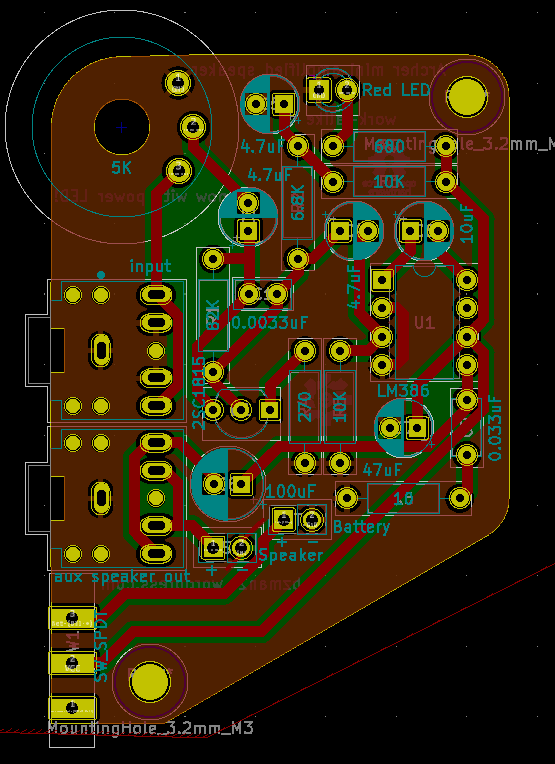
The board is an interesting design, I made it as compact as possible while still incorporating mounting holes and all the ports on one side. I could have gone with some surface mount parts but do you know how many 10k through hole resistors I have? They have to go somewhere.
Something I didn’t realize until right now is that I managed to keep all the traces on one side and except ground. I also kept all the traces as thick as I could so there’s be no tearing them off the board when reworking it.
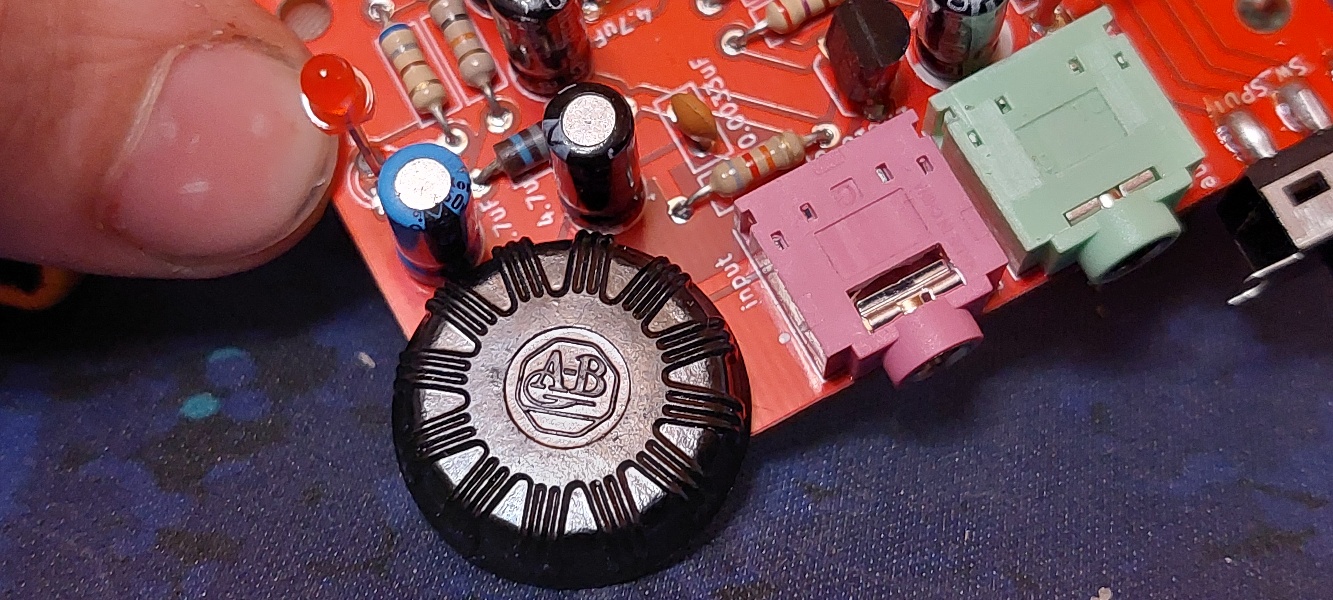
This project did serve as a way for me to use some of these parts. Just look at them, they’re fantastic. These potentiometers aren’t actually the 5K that the original circuit called for, they’re 100K which means that this version has less impedance applied to the circuit it connects to so it will pass more noise. The pot is used as a simple voltage divider though so the range is unaffected in this application.

These switches are also something I’m trying to use up. I have so many parts with a little variance that I’m storing in so many little drawers that I really want to cut down on storing them all. If I can manage to use them in projects, then I don’t have to keep them around. I have used several different switches on the 5 boards I built up and this one is curious. You’d expect because it’s a slider switch that in this position it’s ‘on’. It’s not. The guts of this switch resemble those of a toggle switch where the contacts joined are the ones the lever is *not* pointing at. I have regular toggles too, but this one is backwards. I’m glad I’m using them up.
You may have also noticed that his board is in stylish red silkscreen. I figured this time I’d try out something else from PCBWay since they offered to sponsor this project. I already knew they could do the silkscreen crisp and small, but now I can see how well the white silk shows up on red boards. I think it works pretty well, and if you want something to stand out in a clear case this will certainly do it. Getting boards made from these guys is such a labor saver when it comes to clearing up my parts at home. With code the temptation is to try to write it so you can re-use it forever. With PCBs it used to be such a burden to get boards made professionally that you had to get it right on the first try and they had to work in batches of thousands. I can confidently say if you have 5 of one obscure part and you want to put it to use: design a board. Get it made. Solder the parts in. You are done. You don’t have to spend time drilling, or filing, or whittling with a craft knife to make some strange part fit proto-board. measure it with a $20 pair of calipers, draw it up, and have PCBWay build you a bespoke kit of your very own (parts only included if you ask).
Everything on this board is salvaged, the speakers and switches mean that I’ll have to design and print bespoke enclosures for each one of these. There’s no way this design is just ready to order, but when I get my bed adhesion problem fixed I’ll get some enclosures made and four lucky people can get one of these projects for themselves. If you want to play around with the design it is up on my github, but I do not recommend you just have the gerbers made because I cannot tell you where to find one of those potentiometers aside from my junk drawer. I do genuinely think this is a useful design and I expect that for a reasonable price it could be test equipment people would want, just not 1000 of this particular revision.

Leave a comment