A few months ago I was reading hackaday, like we all do when I ran across a curious article. The article was this one from ch00ftech on reverse engineering the Hit-Clips trendy portable audio technology. I found this odd for several reasons, but mostly because I just assumed everyone knew how they worked. The reasoning for this assumption comes from having torn one apart as a kid, deemed it trivially simple, and gotten bored with it in minutes. I remember quite vividly one christmas (or was it a birthday) when my sister got one as a present and condescendingly sneered that it’s useless ‘without a player’. Oh how wrong she was.
It’s true that you can’t really do anything with just the flash chip sitting there in the palm of your hand, but the player is one of the simplest devices possible. It consists of a speaker, a battery, and a button. All the smarts are located in the chip, the ‘player’ is just a breakout for the chip. I, however have a slightly more interesting piece of retro technology to dissect: a record-able Hit-Clip.
The first thing I would notice is the bright and shiny “Yahoo” logo, this being from the year 2000 those of you that remember the dark times before lord and savior google led us to the light will feel either a wave of nostalgia, or nausea. This device was marketed so that you could record your own sound clips of uselessly short duration and play them back at your leisure. Taking a look at the circuit board one might notice that there is no brain in this player/recorder. There’s hardly any components really, let’s take a closer look.
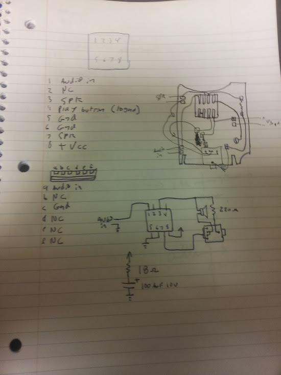
There we have a speaker, headphone jack, two resistors, a capacitor, battery connections, and a card edge connector. The card edge connector has six pins, but only two of them are connected to anything. That connector is the part that makes this particular player unique, that’s the audio input. There’s no fancy serial connection like the computer connected barbie of the same era, those connections are good old-fashioned analog audio. Presumably they didn’t use another headphone jack because the demographic for this product could not be expected to read and understand labels like ‘input’ or ‘output’. I remember (and some checking around will yield the manual) that there is a cradle that this connects to for recording. The battery connection is pretty obvious (and labeled) so I quickly reversed the schematic and came up with this:
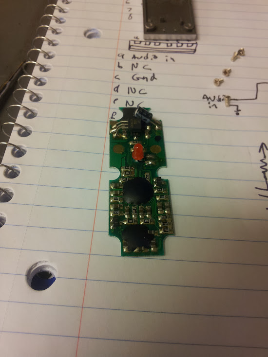
I find it nice that they actually used the switched headphone jack on the bottom correctly so as to mute the speaker when headphones are plugged in. The low-pass filter that was talked about in the more thorough article linked above is simply the mechanics of the speaker, or, on the case of headphones, an in-line resistor. I would have figured the resistor and capacitor wired together would have been in the audio circuit, but they were just on the power lines as a filter. The interesting part about this device is the recording functionality, and while I have pictures of the board inside the module I didn’t reverse the schematic, mostly because I am not going to un-pot the chips anyway so it doesn’t interest me enough to do so. Here it is, the Hit-Clip recorder revealed:
Just because I don’t feel like tracing out that circuit doesn’t mean I’m not interested in seeing it done. I will drop this in a flat rate envelope to anyone who convinces me they are going to reverse engineer it and do a write-up because it would be nice to get that information out there.


September 7, 2021 at 12:54 am |
Hey, I know this was a long time ago, do you happen to have a rough guess at the speaker’s impedence, a resistance measurement would do though it might be written on the back. The hard-wired earpiece ones use seem to be about 100ohm with a 680ohm series resistor so I wouldn’t expect much less than 400ohm.