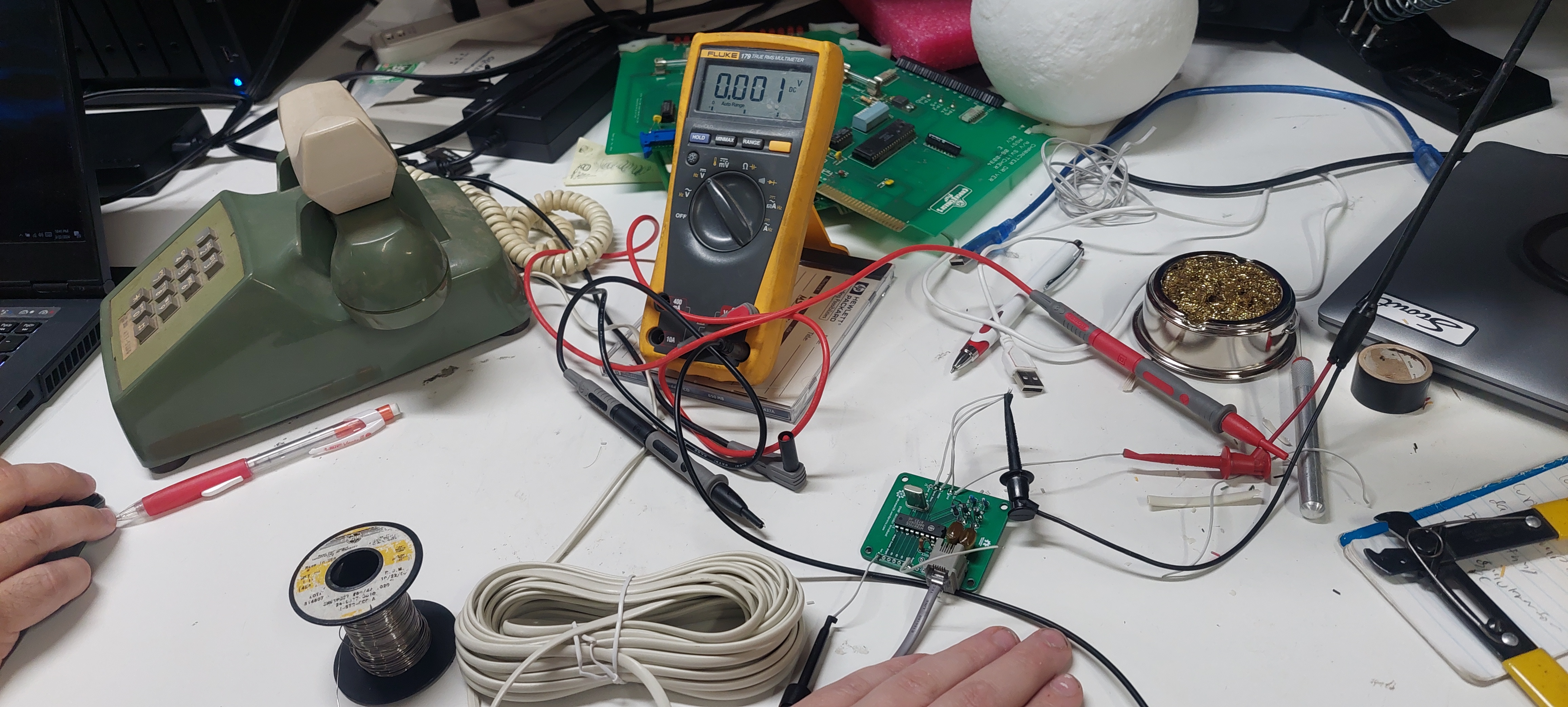
A while back I showed off this board, but I never got around to testing it. Now I have and it works great. There are a couple things to remember about it though. This board sits on an active phone line and listens for DTMF tones. If you don’t want to use it on an active phone line you will need something like a 9 volt battery or other power source to excite your phone to power it enough to generate the DTMF tones. That’s how the device gets its input, but what about the output? You have a number of pins broken out:
- Power Down shuts the chip off when you give it 5v (I recommend grounding it for normal use)
- Inhibit stops telephone service tones (A,B,C,D) it gets 5v (usually don’t worry about this, tie it high if you only want to use a regular phone though
- Output Enable lets the data bus talk, otherwise it won’t output any data (either pull it to 5v or leave it floating, it’ll pull up internally)
- Ready outputs 5v when the data on the output pins is valid, this is important because after a tone is no longer heard the pins stay at the last state they were so this is how to know when there is or is no longer a tone present
- Q1-Q4 are the data pins and a binary representation of which tone is being heard will be output on here. You should really use the Ready line to determine when these can be read for accurate tone detection
That’s it. This device does not produce any tones, it just detects them. If you want to use a phone as an input device it’s actually pretty cool. If you want one of these boards feel free to contact me, or if I run out or you want to make or modify the design then they are still on github here.

Leave a comment