There is a whole whack of these, but there aren’t a ton of changes from one to the next so I’ll go over all the details with the first one, then I’ll only go over the differences from board to board.
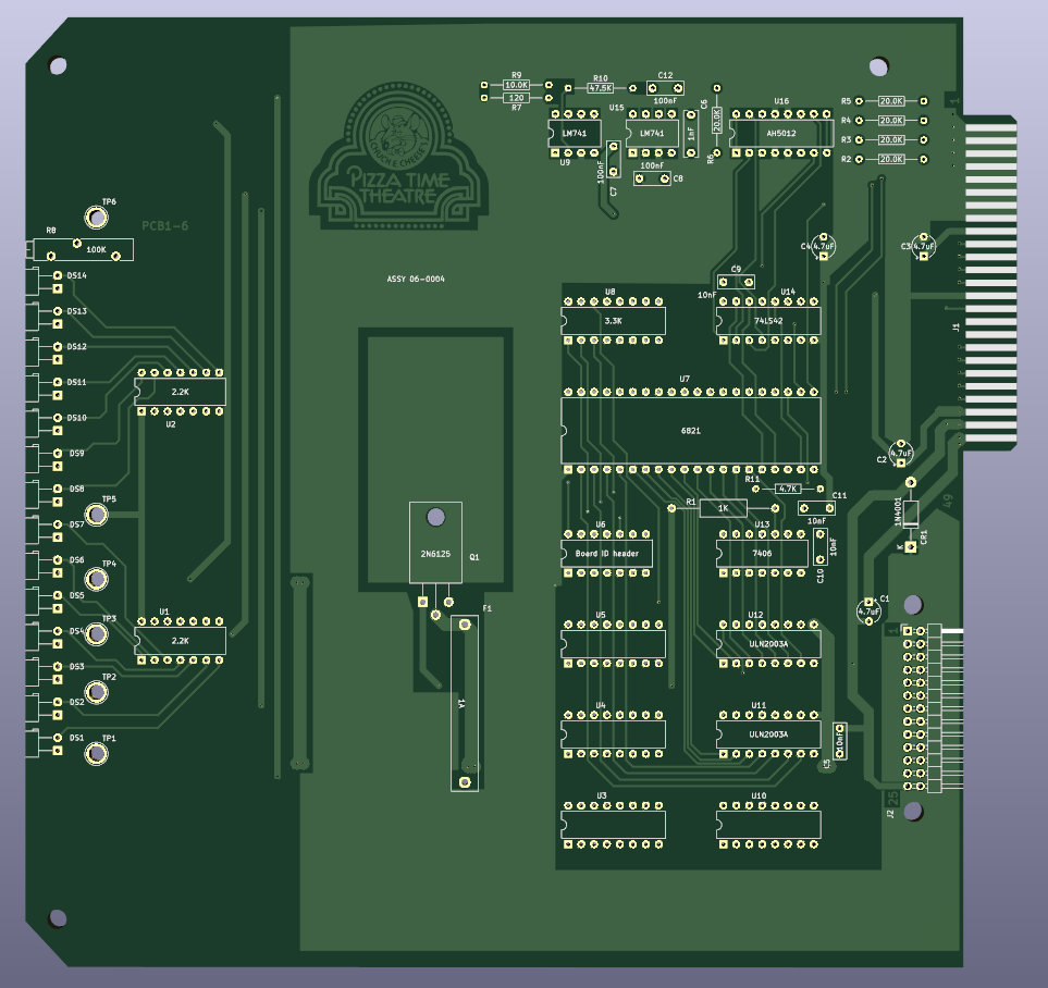
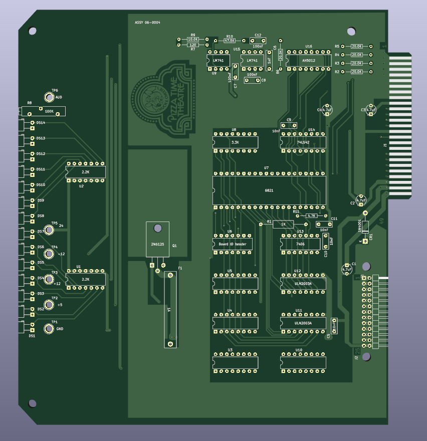
This is the rev.a character board 0004. The only difference between this one and all subsequent boards is this one is about 19mm longer than all the rest. It will fit in the card cage, but it will stick out a bit. The board layout is kind of interesting in that it includes a lot of empty IC sockets for potential bodges that may be needed. Let’s look at the schematic one bit at a time.

On the left we have power coming in and the board ID header. This lets you connect the chip select for the 6821 PIA to one of 10 pins on the card edge so it can be uniquely selected by the CPU card. If you really wanted to you could set two cards the same and have them mirror their movements, but I can’t think of a practical use for that. Then we have CA2 controlling the ‘high’ voltage. It switches the 24v supply out to the character ribbon cable to control all the solenoids out on the character. At the bottom right we have the returns from the solenoids and each can be grounded to complete the circuit for the solenoid. These are tied to LEDs so you can see what movements are being commanded to the animatronics. If the fuse blows these LEDs and the solenoids will not function. This card has 14 outputs, but that’s for a good reason.
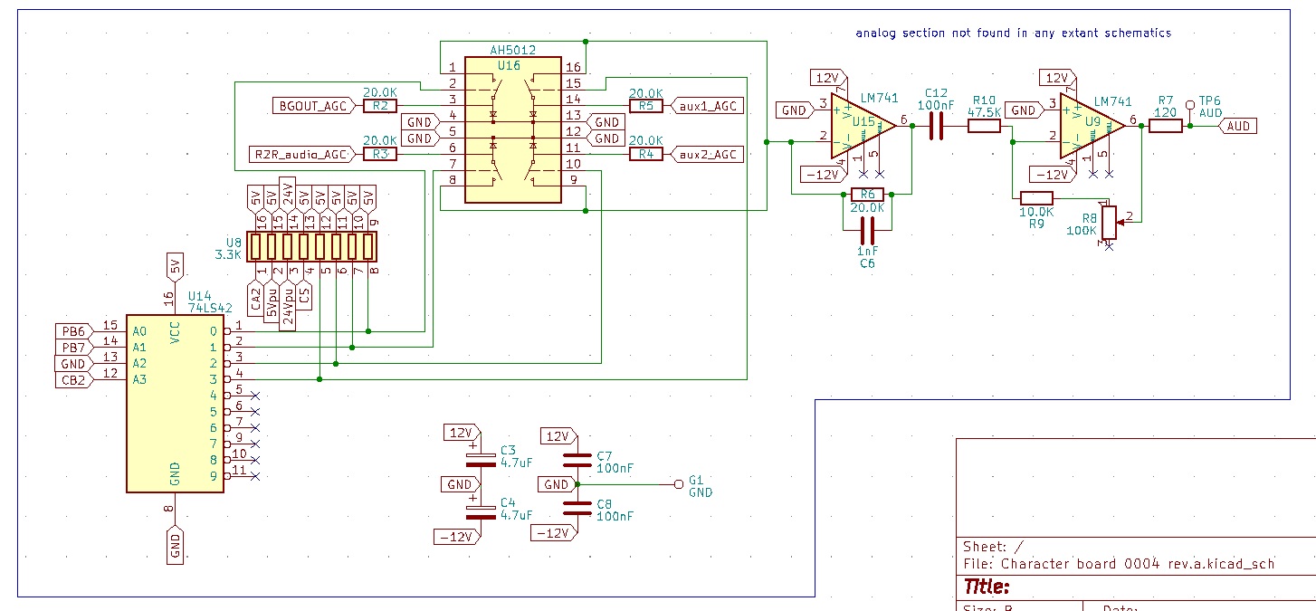
This is the audio section that is only present on the 0004 character cards (I have seen rev.a and rev.b). This works with the 0003 audio card to choose one of four audio tracks to play. I know it only chooses one because it uses a 74ls42 to pick and that chip has mutually exclusive outputs. In this case the remaining 2 bits of the PIA are being used to pick which track, and CB2 is being used to enable audio at all. Once the track is selected (I suspect it’s 3 tracks from a reel to reel and one for mirroring the background game room audio) it gets amplified and volume controlled before exiting the card onto pin 2 of the character connector.
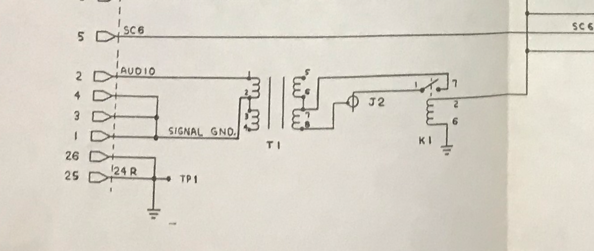
This is the circuit on the solenoid driver card. It seems to be a matching, or isolation transformer and a relay controlled by the 24v line to the solenoid card. I don’t know if there was supposed to be an amplifier at the character, or it was just a speaker coil, but this is how these characters worked. If you have the more modern 0033 audio card this output would still work because two of the four channels are still available to be chosen from (one being the reel to reel, the other being the background audio). The ROM that’s driving your unit just had to control the audio on the character card, which the one that we have disassembled does.
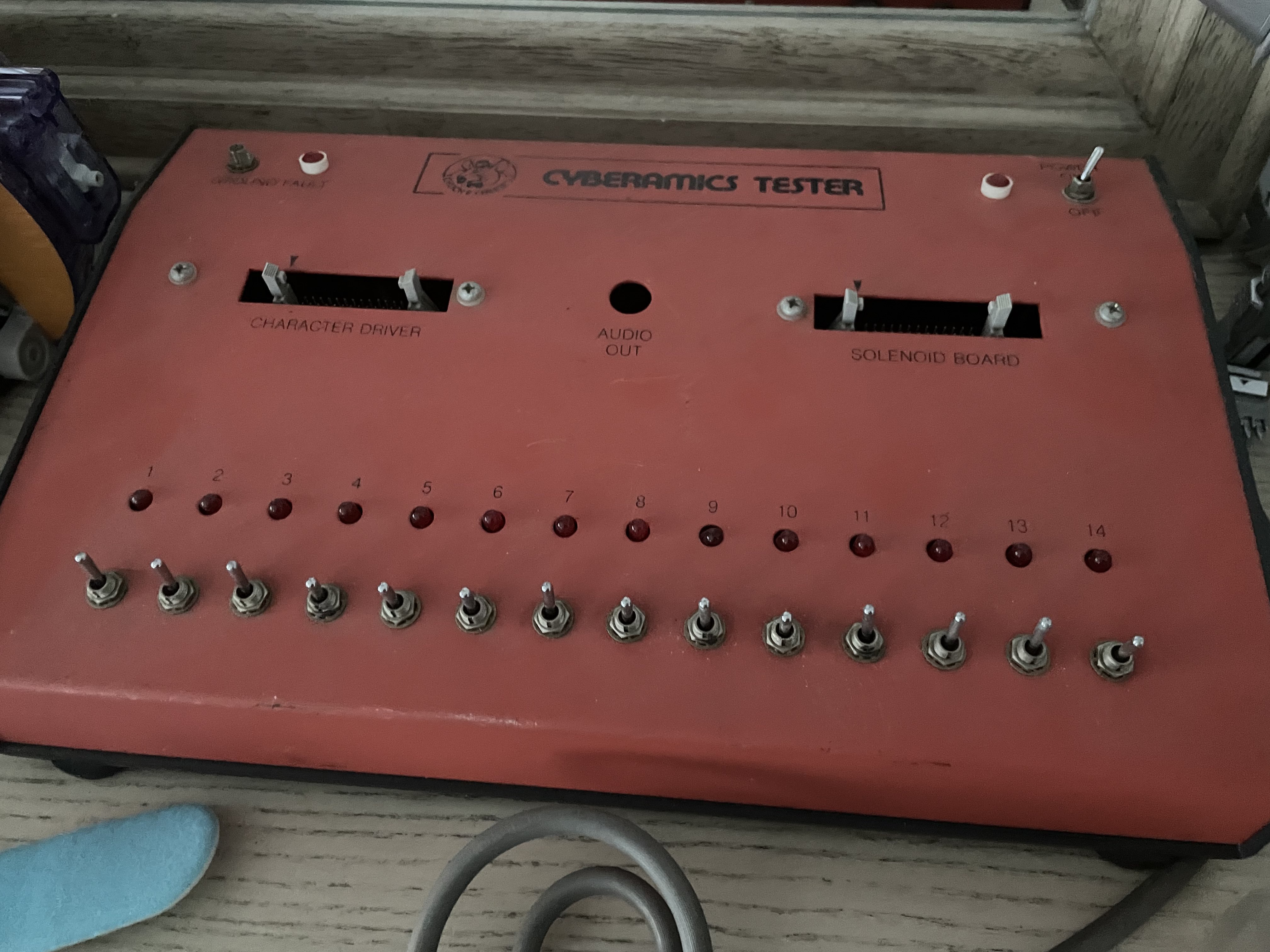
This cyberamic tester now makes more sense. It seems to sit between the computer and the animatronic to indicate what solenoids are trying to energize, over-riding them, and also having an output for the audio signal.
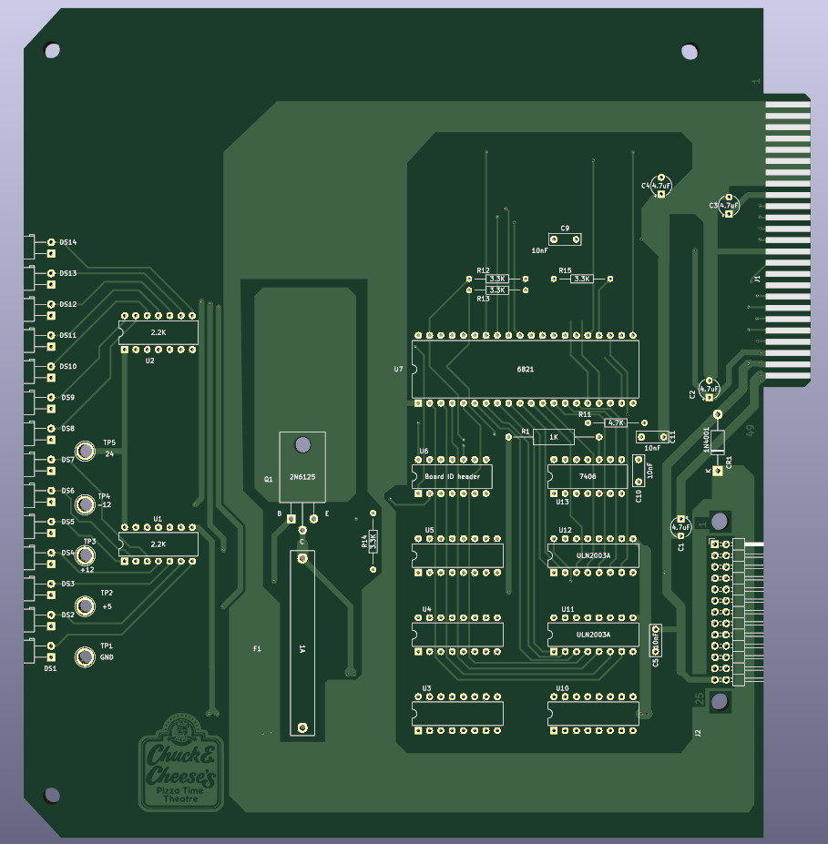
0004 rev.b really just changed the board length. There’s nothing else of note, but this is the standard board size going forward.
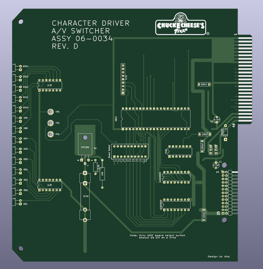
0034 rev.a dropped the analog portion. It does not re-use the outputs controlling it however, so if you want to run the same code that twiddles those bits that is perfectly safe, it just does not do anything. They updated the logo to this square one, and removed one DIP resistor pack in favor of individual resistors as there are less than a full pack being used with the audio stuff gone. The 12v and -12v stuff from the audio stuff still exists, but it just has capacitors and test points on this board, neither of which are needed for this card’s functionality. This card is intended to pair with 0033 audio cards because those do not need the character cards to handle the audio, but as stated above they still can, but for 2-channel functionality instead of 4).
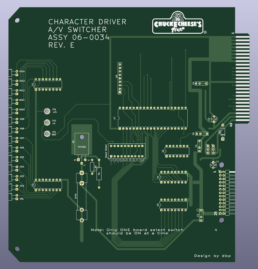
0034 rev.d is a major overhaul and the first post-1993 board I’ve done a reproduction of. There are a bunch of changes, but largely not to the functionality. The solder-in fuse has been replaced with a fuse holder, the transistor was changed to a more modern TIP130A, and the spare chip locations are gone. All the 12v and -12v stuff is gone because this board doesn’t really share that same heritage and got a big facelift. The main chip is the same, but the IC socket with jumper packs to select only one board ID is replaced with a set of dip switches with a stern warning to only select one at a time. That is because the chip driving all those chip selects is a 74LS42 which drives one output low and all the other outputs high. Selecting multiple IDs at once would connect 5v and ground together and that wouldn’t be good. The other major change is a set of jumpers that you can connect to make he output voltage 24v or 5v. This is because the character cards from this generation were re-used as general purpose output pins to control an external A/V switcher. This generation did not use the audio card at all. Those resistors that were split off before are now back together in a SIP resistor pack. There is also a new logo, but this time it’s on the silkscreen.
The last character card I have seen is the 0034 rev.e board. There are only minimal changes from the last one. The capacitors are now multi-footprint so you can populate them with two different pin-spacing parts depending on what you have. The 24v/5v jumpers now have a default position of 25v and you have to cut the copper to get a 5v board. The silk now has different reference designators, and the underlying references may have changed in the last revision but the silk had values there and not the references. There’s also a sort of unexplained track re-routing. These tracks seem to dart around some non-existent chips, and since I know what the immediate previous version was, I have to assume this was maybe to add some other function but it was dropped.
That’s it, that’s all there is for the character cards. I have versions of all of these up on github, but there’s really only two you might want. If you need audio functionality, use 0004 rev.b as it’s the right length. If you do not need audio functionality and you want the modern amenities go with 0034 rev.d. I’m not sure how I feel about dip switches, if you don’t realize which way is ‘on’ you may accidentally short it out. I will be continuing to explain the subsystems and functionality of the cyberamic control system in upcoming posts (I think I only have one more). Feel free to ask me about any issues you may have with one of these setups. I may know something after digging so deep into all this.

April 3, 2024 at 1:01 pm |
[…] Hacks, repairs, arcade games, sci-fi, and some very bad ideas with possibly humorous consequences « Cyberamic control computer character board […]