The third board I’m going to try to explain is the audio board. This one was harder to do than the others because even though the transport board had an incorrect and incomplete schematic, this board had no schematics. That means I had to put together these replicas based on a bunch of reasonably good pictures, some measurements done at the museum who let us have some time with the cards, the disassembled code, and the other cards for reference. This ends up being a big puzzle figuring out where all the connections go, and sometimes it takes some looking at the datasheets for the parts and saying ‘well, this has to be pulled high otherwise it would never work’ and just rolling with it.
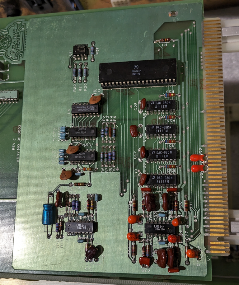
The first card I want to talk about is the 06-0003 rev.c board. I only have rev.c of this board, but it is clearly the earlier board. It has two main functions, measuring the room audio level, and controlling the volume of all the audio channels. We’ll start with the first part.
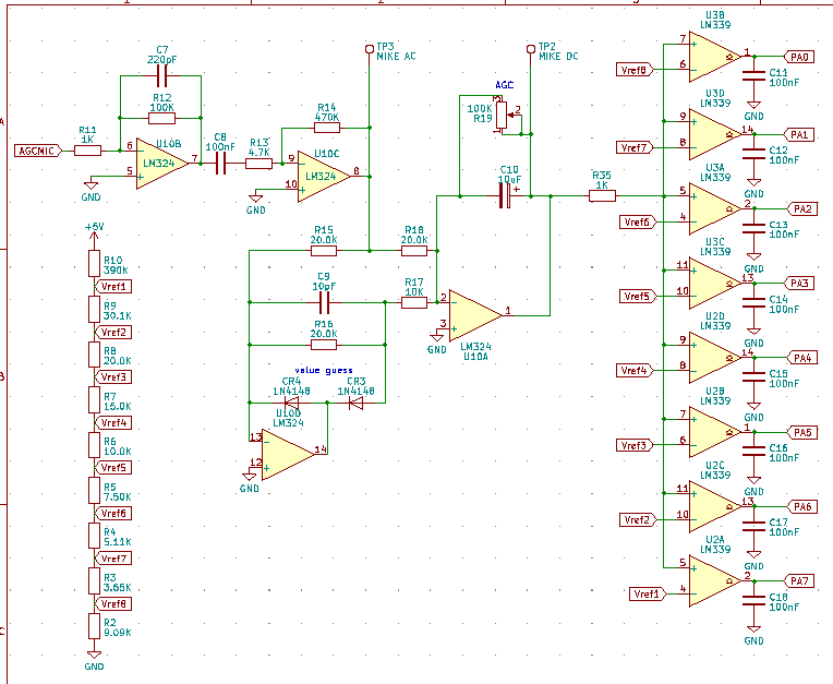
This is the automatic gain control microphone input. I don’t know exactly what all the filtering is doing but I know the main thrust of what’s happening. The room audio is picked up, amplified, filtered in what I assume is an envelope circuit to get a nice smooth analog value for the average room volume. That audio is fed into 8 comparators that compare the analog room audio level to a set of fixed voltage offsets coming from that large resistor ladder with many taps. This produces one of 9 states, either the audio level is below the first comparator, or it is at or above the level of any of the comparators in the chain. This is not a binary counter sort of situation, if it is halfway up the possible volumes then the bottom 4 comparators are all detecting it.
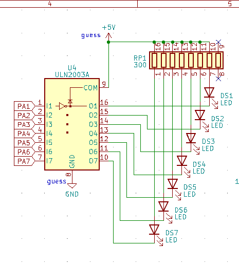
The 7 most significant bits of this are put directly on the LEDs on the front of the card. Even with no CPU installed, this circuitry will detect the room audio and present it on the LEDs. That data is then fed to the onboard 6821 PIA chip so the state can be read by the CPU. Once the CPU decides what to do with the audio streams based on the ambient audio level and the automatic gain control knob on the front panel (or a possibly just a table lookup in some versions) it commands the DAC chips to control the audio levels.
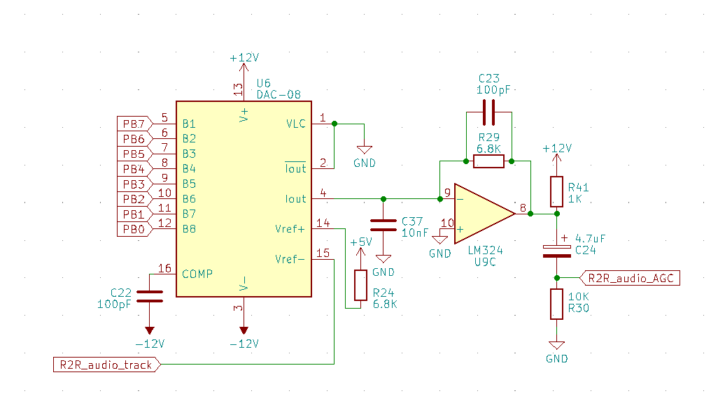
There are four sections on this card that look identical to this. This operates in an… interesting way. I would expect a digital to analog converter to take a purely digital signal and reproduce it between a high and a low fixed threshold. That is not what this does. One of the threshold pins is fed analog audio and the output is that audio, but gain controlled to 256 possible levels. I suppose you can use a DAC with external Vref pins as a fancy volume control, but I didn’t expect that. I said there are 4 of these circuits, so that means 4 input pins for 4 analog audio sources and 4 pins on the card edge connector to put the 4 gain controlled audio signals. There is one slightly different channel though.
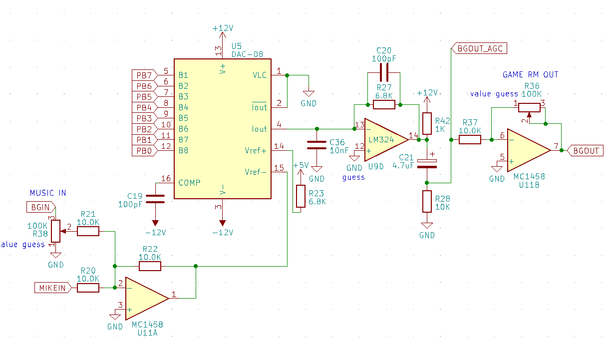
This one takes the background audio (game room music) in with its own volume pot to set the relative level. It mixes it with the microphone input, not the AGC mic, but the microphone where an employee might make announcements. That audio then passes through the same amplification stage as the rest, including going out to one of 4 pins on the bus for gain controlled audio. This stream just also passes through another amplification stage with its own volume control pot and goes out a separate output dedicated for the background audio. The output here always has the combination of game room audio and microphone going out, it just gets volume controlled by the AGC circuitry.
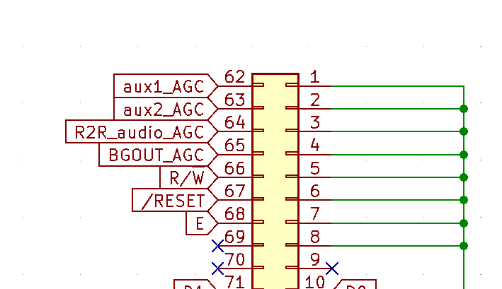
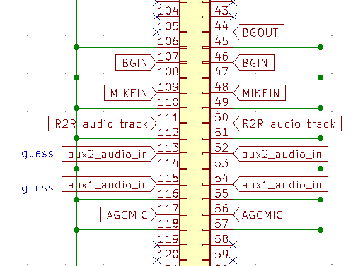
Up at the top of the connector are the 4 channels of audio that go out on the bus, all amplified equally. At the bottom you can see the analog channels in and out. I have only labeled one of them R2R audio meaning reel to reel because the cable setups I have seen only have that pin carrying the audio from the reel to reel show tape. Where do the other channels come from? I don’t know.
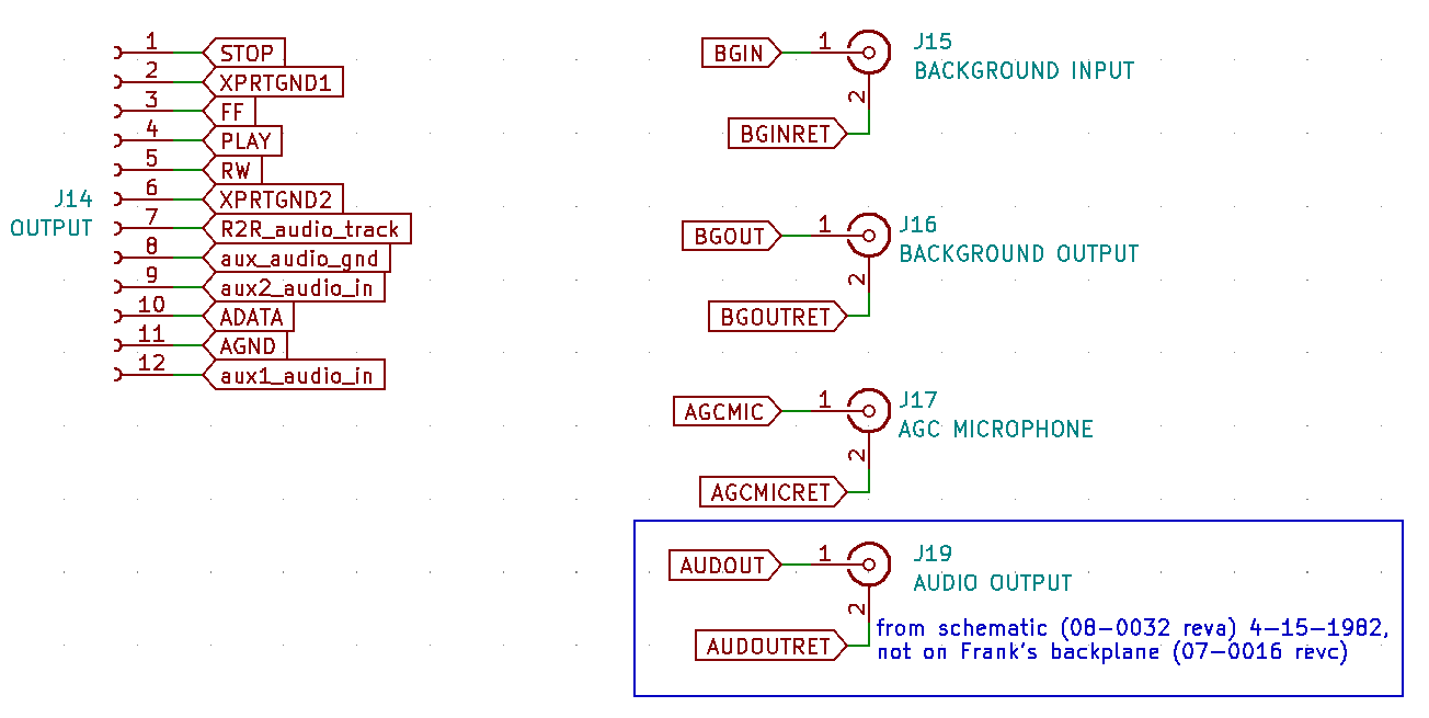
This is that section of the backplane schematic. Ignore J19 for now, this card does not use that. The backplane has 3 RCA connectors for the background audio in and out, the microphone for AGC, and not pictured is the employee announcement microphone that looks like it comes in from the big power supply/button unit. J14 is a big Molex connector that has a cable that goes to the reel to reel machine. On the one in the museum the pins for aux audio are not populated, I only determined that’s what they do from looking at how this card functions. The reel to reel already has two tracks, one for data and one for audio. Was this originally used with a 4-track reel to reel machine with 3 audio tracks that could play in parallel? Maybe, but I’ve never seen documentation that indicates that or tapes with 4 channels of audio. How does the audio get out of this card cage? Well, for this card (0003) you need to pair it with the older character card (0004) and on those cards they decode which of the 4 audio tracks to output and output them locally at the character. I’ll get to that in my next entry.
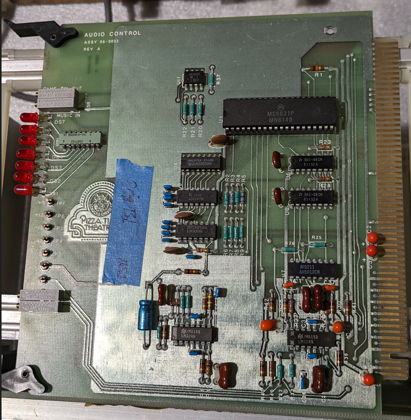
The next card I have is 0033 rev.a. Note the extra 3 in the tens place, this card is not a predecessor to the last card, it is a successor and is not fully backwards compatible with it. The AGC functionality is the same, but only two of the audio amplification sections are present. Those sections then do this:
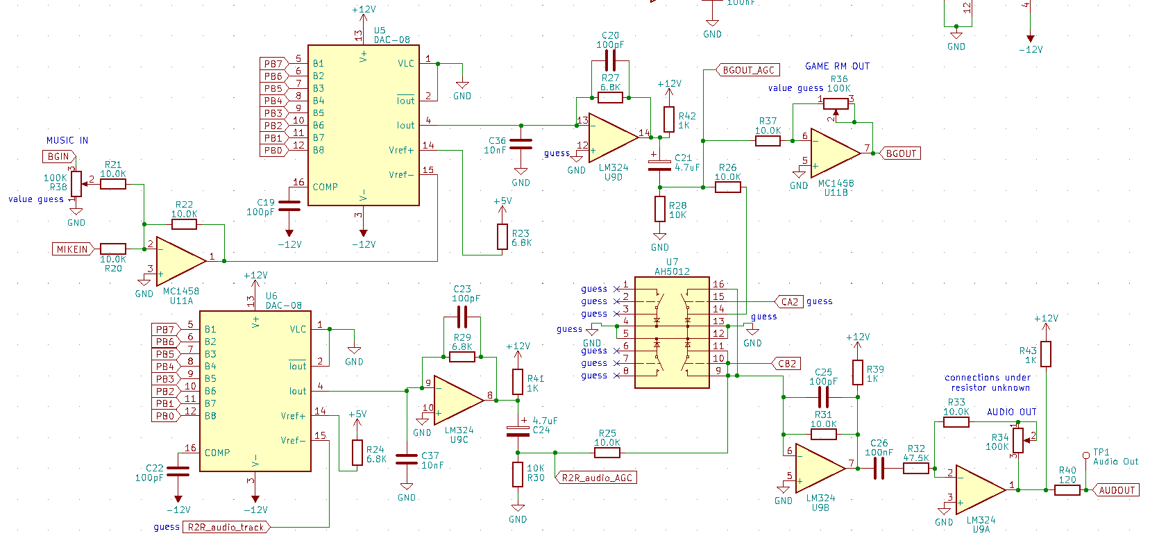
If you squint you can see the similarities. The background audio and reel to reel audio sections are the same. At the point they go out on to the card edge connector (which still happens) they are also connected to this analog switch. This switch picks which audio channel will go out the new mixed output. The way it’s wired we could have one or both or neither output, but I suspect they are never both output at once. This means that the single audio output either functions like the room speakers, or it puts out the show audio instead while a show is running. The output stage re-uses the two op-amps from the now missing aux channels and tit has its own volume pot for setting the level. This audio does go out J19 on the backplane.
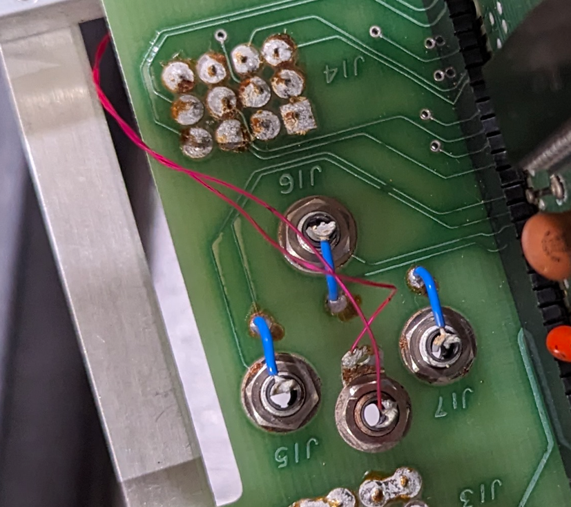
Here’s the thing, I’ve never seen a backplane with J19. It’s always added by hand like this, and this is the third backplane I’ve checked. Clearly the backplane was designed for the 0003 board that didn’t need this and was retrofitted, but were any backplanes produced with J19 installed? the schematic I have has it on there.
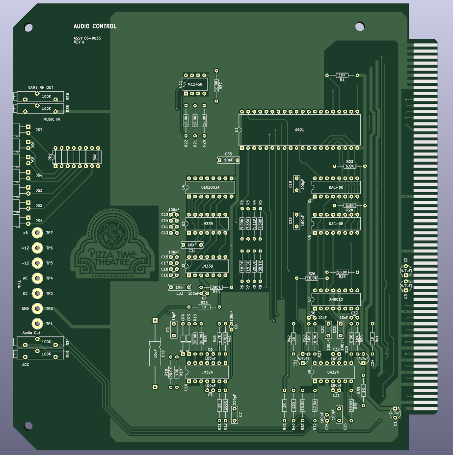
There are some routing choices that make it obvious that 0033 came later and was modified to suit. The wires that just chop through the ground plane there at the bottom for one. There’s also some traces on the back of the board that dodge chips no longer present and connections that used to be for the other two analog audio inputs. Here’s some important things to note:
If you have a 0003 audio board
- you must use it with 0004 series character cards
- the character audio comes out those cards
- you are compatible with 4-channel recordings (early?)
If you have a 0033 audio board
- you can use any character card
- the character audio comes out J19 on the backplane
- you are only compatible with two-channel reel-to-reel recordings
The ROMs Frank and I have disassembled have code that controls both the audio switching on the character cards and the audio switching on the audio board. This makes it universal and can work in either setup. The ROMs we have are only for The King configuration, however, so it remains to be seen what additional control is done to handle other character audio.
I think it’s super cool to be able to have the audio come out of the animatronic that’s currently talking, as well as having multiple channels that can talk over/with each other. Apparently this was used for some early setups, but did not stick around as the audio from the characters was not loud enough. As always the cyberamic stuff is all on github here. I will be continuing to explain the subsystems and functionality of the cyberamic control system in upcoming posts. Feel free to ask me about any issues you may have with one of these setups. I may know something after digging so deep into all this.

Leave a comment