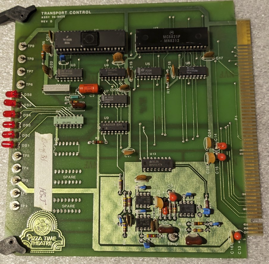
The second board I’m going to talk about in this series is the transport board. This board controls the Teac X-7 reel-to-reel machine and processes the audio from one of the tracks into serial data. This one I have a schematic for, but it’s not for any version that I think existed for real. It has some clues to a version I don’t have and shows a feature of a later revision that I do.
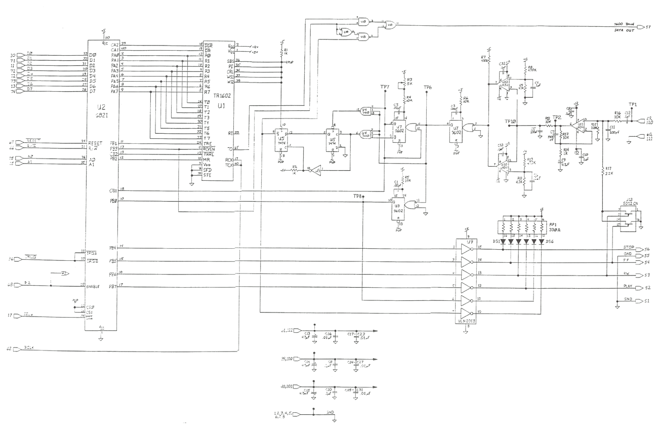
Like most boards other than the processor, this board is based off of a 6821 Parallel Interface Adapter. Connected to that is a TR1602 UART serial chip. Think of this as something similar to your standard 8250 or 8251 that you find in a lot of Z80 designs. That chip is hooked to a whole bunch of analog circuitry that takes audio and turns it into sensible serial data. There are some errors on this schematic though.
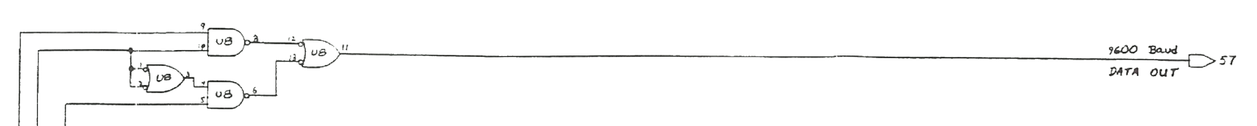
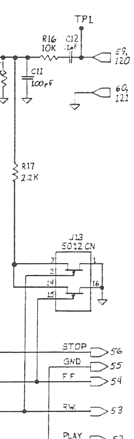
This section at the top of the schematic does not exist on either the revision B or the revision D board that I have seen. It would work to output a serial data stream there, but on the real machine it would only be at 4800 baud. Pin 57 is not used for anything on either of the transport cards I have seen, and it is not hooked up on any backplane I have seen, so it’s possible this was dropped early on in the design.
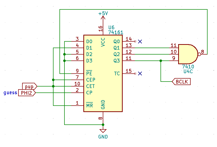
The schematic claims to get the serial clock from an external card edge pin, but the boards I have both use this circuit. I haven’t been able to verify that it is wired exactly like this, but it’s a best guess from pictures and context clues. This is a divide-by-13 counter and that makes the serial clock from the CPU clock. The pin that it claims to get the clock from is used for an auxiliary audio source on some cards I have, so perhaps there was an idea to use this serial port in a synchronous mode where the clock and data are both provided by the same source? I don’t have hardware that would support that other than speculation, and the schematic has no conditioning circuitry to adapt what would have been an analog waveform into a digital clock, but that’s my only guess for why the schematic places the clock input there.
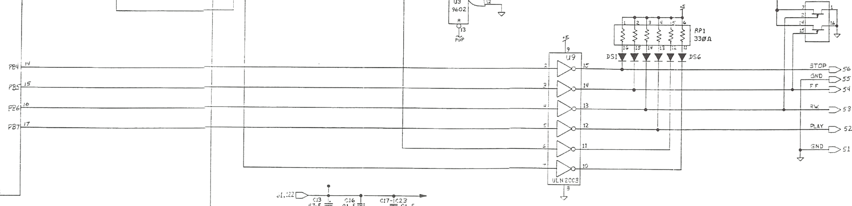
The lights on the front of this card indicate how it’s currently controlling the reel-to-reel machine with the stop, fast forward, rewind, and play functions. There’s also two extra LEDs that indicate if there is a carrier and show the serial data being received.
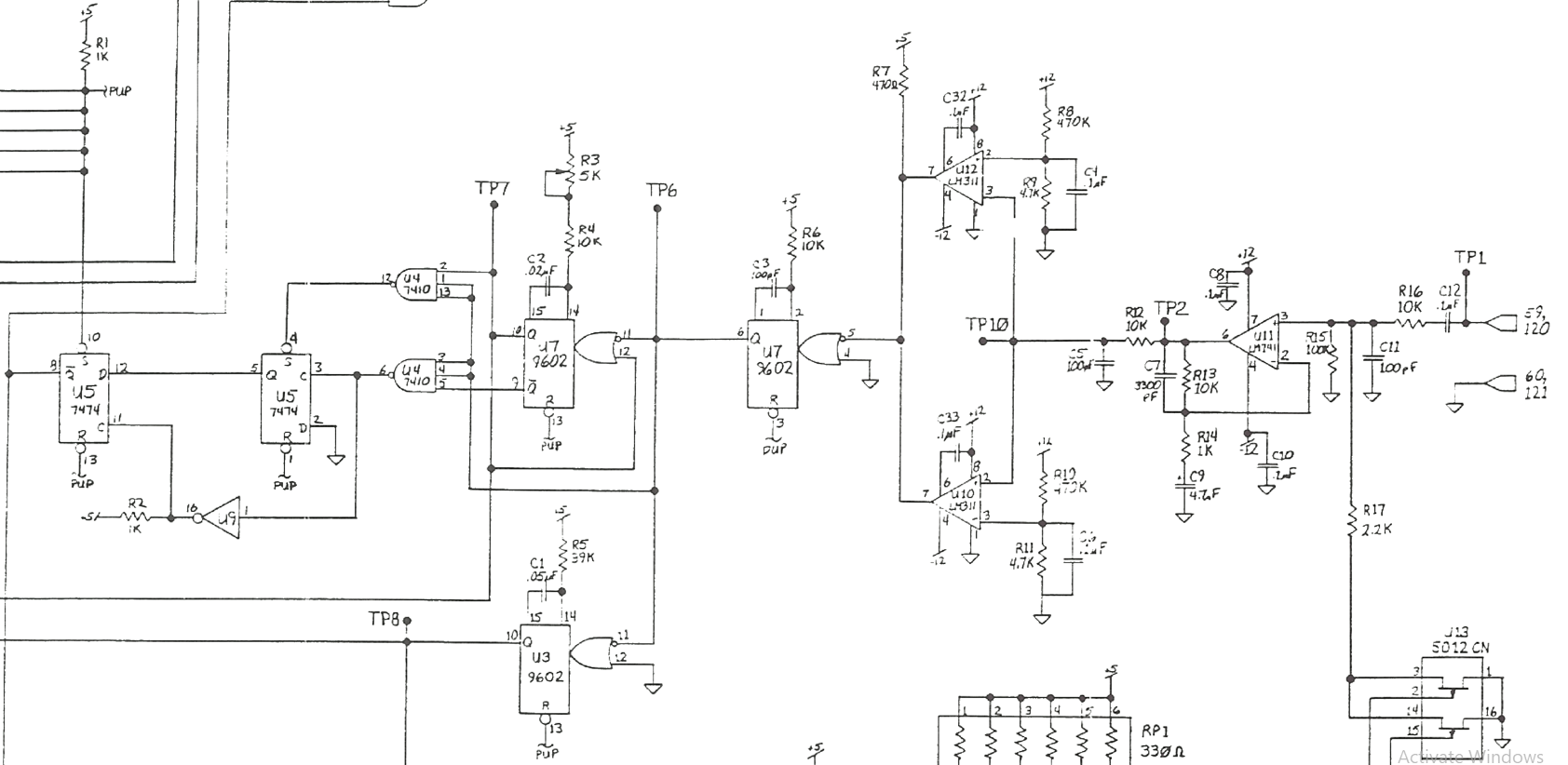
The serial data conversion from the analog waveform I can only speak about in high level terms. From what Frank told me and what I can see here the audio gets filtered, the zero crossings are then detected, some timers similar to 74LS123s generate and detect pulses of the required length for bits of data at 4800 baud, and from that we can see if there is serial data available or even count the zero crossings manually.
There’s also another chip that pulls the audio input volume down if the card is commanding the reel to reel deck to run in fast forward or reverse. That’s pretty odd considering the Teac deck has circuitry to mute the output whenever it is in either of those modes. There’s a clue though, in the bill of materials for constructing one of these systems it asks for the specific reel to reel machine:
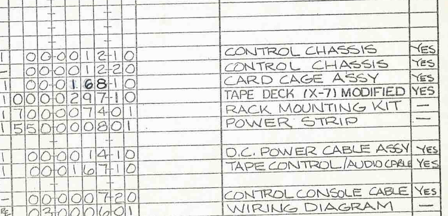
What does it mean that the tape deck is ‘modified’? Well, After a discussion between Frank and someone very knowledgeable about these things it turns out that one resistor is shorted in the deck and that disables the muting of audio during fast forward and reverse. But why would they do that? It turns out that there is a low 21 Hz tone encoded between segments of the tape, at least for the tapes meant for ‘The King’ or other single animatronic character shows. These tones are sped up and amplified when the deck is running in fast forward or reverse. The code in the ROM looks for that tone and uses it to determine where it is in the tape (how many shows are left) and when it hits the end it uses that to detect a long pulse at the beginning of the tape so it can stop rewinding. Based on the hardware and the code that frequency can be anywhere between 166Hz and around 3200Hz. A very forgiving range to account for the differences in speed of the rewind and fast forward mechanism.
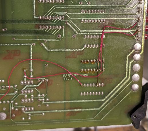
The real cards aren’t so pristine as this schematic shows. The revision B card doesn’t have that function to lower the volume of the incoming audio. That seems to have been added to account for the fact that the tone on the tape was amplified when it runs fast across the heads. Without it the input amplifiers on the card may be overwhelmed and cause some errors in detecting where to stop the tape
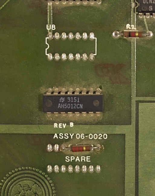
There’s also a spot for a chip labeled U8, but no traces other than power and ground go there. Unused chip locations on these boards are labeled ‘SPARE’ as you can see, U8 looks to be a leftover from when this board put out the serial stream on pin 57 as indicated in the schematic.
Revision D incorporated that chip into the main board design, but it retains the U8 designator. I suspect that chip was on the revision A board but removed after that because nothing else in the system needed the serial data. This board connects the interrupt line to the same pin that the CPU card has, but the backplane doesn’t connect them. If you wanted to you could wire wrap a connection for it, but the tape data speed is slow enough that the CPU doesn’t need an interrupt. Maybe that’s a leftover from the planned 9600 baud?
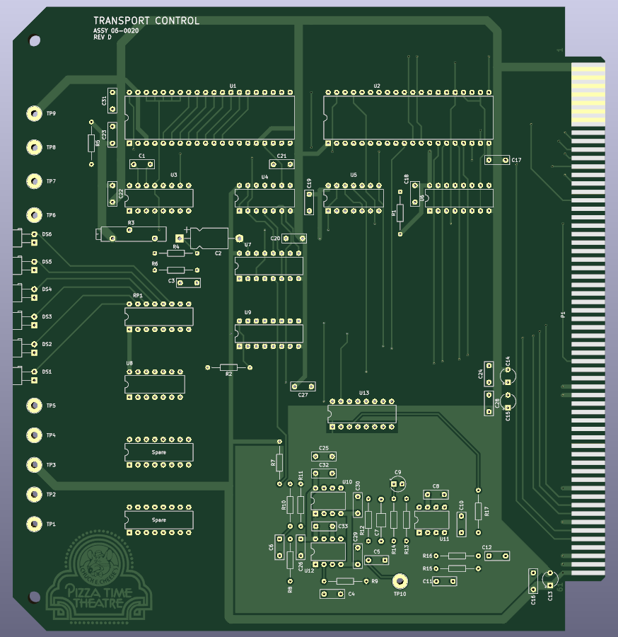
I have a full replica of both versions of the board. If you’re going to make one I suggest revision D because it contains all the features. If it were me I’d also add a bunch of silkscreen to explain the LED functions and the test points (and the values for the components), but that breaks from the authenticity of the recreation. Thanks to Selena for helping me convert the logo to monochrome in the right way to make this board authentic. This is not the only time I would need that sort of help. If you need one of these board I can make you one, or you can find the design up on github here. I will be continuing to explain the subsystems and functionality of the cyberamic control system in upcoming posts. Feel free to ask me about any issues you may have with one of these setups. I may know something after digging so deep into all this.

April 3, 2024 at 1:48 am |
[…] Hacks, repairs, arcade games, sci-fi, and some very bad ideas with possibly humorous consequences « Cyberamic control computer transport board […]