Archive for February, 2019

Eurocom laptop backlight repair (bypass?)

February 20, 2019

So, there was a small issue with my laptop.  It was dirty.  I cleaned the screen with glass cleaner and wasn’t too careful about where the liquid got.  Later that night the screen fizzles out.  In summary The not-water part of the cleaner corroded on the LCD connector on the display and no matter how much I cleaned it I couldn’t get it all functional.  I ordered a replacement panel (LTN156FL02-101) and a replacement cable (6-43-P7501-022-1C) from ebay and aliexpress respectively.  The panel came in first and I was excited to install it, in that excitement I tried seating the old laptop cable on the new (used) panel a couple of times and eventually I stopped getting backlight and smelled electronics burning (oops).

eurocom backlight circuit

Luckily this is a Eurocom, which means it’s a rebranded Clevo, which means I can get the schematics for it.  I have the schematics for the P775DM2(-G) and mine is a P751DM2-G and this section is the same between them.  Above is the chip that I found charred and destroyed.  The MTS3572G6 was burnt to a crisp.  I tried to order one but ebay had none, digikey had none, aliexpress had none, it seems to be a very specialized part (N-channel P-channel pair, like a darlington).  I could have gotten some similar FETs and bodged them back in, but after reviewing the circuit it seems that all this does is turn on the backlight.  Before I did this I had no idea if this would mean that it would always have the backlight on when the lid was closed, or other un-intended consequences.  But I also saw this:

edp circuit.PNG

This shows that the panel handles the brightness on its own, and even has a backlight-on line, the part of the circuit that fried seems to let the video card turn off the power to the backlight to save power (I’m guessing).  Based on all this bridging PJ45 would seem to fix my issue.  But if it happens again I’ll break something upstream and I don’t want that.  I could install a fuse at the jumper, but what reating? The burnt chip is good for… 20A? That won’t do (and I don’t believe it).  What are the ratings on the panel then.

backlight.PNG

Looks like 900mA.  I picked the next up size polyfuse (1100mA) and got to soldering.  It’s not pretty.

20190211_225919

That connector at the bottom is the graphics card socket, this all had to fit under the graphics card.  After re-assembling this thing for the tenth time in a week it boots up!  The new screen has a stuck pixel but that’s what I get for buying used instead of new.  The un-intended consequence is that I now have screen on boot every time.  Previously, when not in UEFI mode the screen would not light up if the laptop had been on recently (20 minutes or so).  I never found the root cause of this, but once windows 7 booted and the driver asserted the graphics card everything was fine.  Now it seems the display is always on for boot.  Don’t ask me why it used to have a cooldown time, I tried everything including removing the bios battery and resetting to factory defaults.  This jumper happened to fix all the problems I had with this laptop.
Printer motor controller reverse-engineer (ish)

February 20, 2019
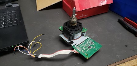
20190220_021719

How it came out of my junk box

Back in college we salvaged and gutted an old roll around printer.  Inside were like a million magnetic clutches, a bunch of rods, belts, and gears, and some of these motors.  The motor is self contained with its own control board and the silkscreen is labeled but the chip returns no results when googled.  Here is how to make it move:

20190220_021742

That blue capacitor was a guess at the value, it’s on the 24v line and the original fell off years ago

Inputs:

HL – High/Low? needs to be 5V

Lock – magnetic clutch? dunno, but it’s getting the complement of the clock signal

Clock – speed input speed control, 5v square wave (10-600hz)

S/S – start/stop? dunno, bogs down when pulled up or down, seems to speed up a bit when tied to clock

GND – logic ground

+5V – logic supply

G24 – motor ground

+24V – motor supply

The chip is labeled: HFENGINE / VG30DSP / 4CA8G and I had no luck locating it with google.  This is a functional implementation, but probably not optimal.  It was a crapshoot even trying the complement of the clock signal on some of the lines and it seems to be stable.

20190220_024329

working

Scanning Electron Microscope repair – CA3098E replacement

February 2, 2019

So, a buddy of mine just picked up an Amray SEM.  I have no idea what model, but apparently there’s a mailing list community of hobbyist and they’ve never heard of this particular model.  That’s a good sign.  After trying to set it up several problems were found and fixed (I’ve got to start documenting things again) we came across this poser.  There are four thermocouple inputs on the board, amplified with some opamps, and that signal is piped to a single display (galvanometer) via some analog switches.  None of that interfaces with the microprocessor, except for the fact that all four analog signals (post amplification) run into four of these CA3098E hardware hysteresis chips.  Simulating a signal for the thermocouple using a 10 turn potentiometer and a AA battery we found that the hysteresis chips were not doing what they should.  The datasheet is pretty clear that there’s a high and low setpoint, and input and an output, and the output was not changing when the input went above or below the setpoints.  We really didn’t have a way to tell what else it should be doing so we declared them bad.

With no source for these chips other than some from e-bay which were probably salvage anyway we resolved to build a replacement.  The first thing that came to mind is using a literal textbook as reference to build the textbook op-amp hysteresis circuit.  There was a problem with this approach: despite thinking we came up with the right equations it did not simulate right in LTspice.  In the end it ended up that comparators are different than opamps in ways this circuit cares about, but it only took like three hours to figure that out.  The problem I had with that circuit was that it only used one setpoint and some carefully calculated resistor values, I’d rather it be a real drop-in replacement for the original chip and take the two setpoints that the board has trimpots for so it could take the original chips if we come across ones we want to use.

img_20181223_001103

Matt’s circuit, smaller but requires a different setpoint and if you want to change it you have to recalculate those resistors

My circuit is an example of brute force in electrical engineering.  No calculations, no carefully picked resistor values, just building blocks.  Problem statement: we take one input and two setpoints, switch the output high when the input goes over the first setpoint and the output only goes low when it goes below the second setpoint.  The output of the entire circuit is open collector and can be pulled up to whatever the output wants, which is useful for someone working with chips that are basically only good to 5v.  To me this sounds a lot like an SR latch, you set the output high with one pin and reset it (set it low) with the other.  You can build this latch out of NOR gates, I used NAND because we have buckets of 7400 chips I wanted to use up.  To drive the 7400 chip I needed a 5v rail derived from the 15v that drives the chip.  Rather than using a linear regulator which would burn a lot of that as heat I opted for an off the shelf buck converter hardwired as a 5v output (the practical upside of which is that there is now a usb port inside the machine if you need it for anything).  The comparators that drive the input of those are an LM339 (good to 15v) and I used three out of the four in the overall design.  The output of the latch is used to drive that third comparator which is compared against a resistor divider making half of the 7400’s power rail so it simply follows the output.  This buffer is to give the output of the circuit an open collector output as the 339 is just that (I’ll have to remember that trick when interfacing with different voltage systems).

img_20181223_115557

My circuit, bulky but perfectly replicates the subset of this chip that we actually use

The final design goes like this:

Input goes to one input on comparator A and one input on comparator B

setpoint A goes to the other input on comparator A

setpoint B goes to the other input on comparator B

15v drives the comparator and the buck converter to generate the 5v rail

comparator A and B are the inputs to the 7400 SR latch (pulled up to 5v since they are open collector)

5v rail is used to drive the 7400 and generate the 2.5v reference voltage

one of the outputs of the SR latch goes to comparator C

the 2.5v reference voltage goes to the other input of comparator C

the output of comparator C is the output of the circuit (pull up to the right voltage is on the PCB we’re interfacing to

This circuit is a real challenge because you can flip the polarity at basically any point, and I have purposely left out any mention of which is correct because I don’t remember what I did but at one point it was wrong and at another point I fixed it somehow.  You also have another two NAND gates to use which can be used as NOT gates if you don’t want to swap the inputs on a comparator you wired wrong.  This is an interesting project for using analog and digital components as well as interfacing to an existing circuit without using any programmable parts.

bttf3

Yeah, my fix is kinda like this