Recently we had a problem at work, we were using a specific watchdog timer and it became unavailable. The people who were supposed to source it suggested an alternative which turned out to not do anything close to what we wanted and I was presented with a problem: find or make a replacement for the watchdog timer we were using. The first thing I did was try to find an equivalent, which did not appear to exist, and then it was suggested that I make one using an arduino. That would be relatively simple, but with this being a safety oriented design I don’t want the entire stack of the arduino libraries, compiler, assembler and other junk becoming a possible source of issues that I couldn’t anticipate. So I decided to make one out of discrete components.

This would have been a lot faster to build
The module we had before had several parameters I needed to replicate and one that I threw out for simplicity’s sake.
- Powered off of a 5v usb port
- Take a 24v ~50% duty cycle signal as a heartbeat
- Turn a relay on if the heartbeat goes away
- Turn the relay off when the heartbeat resumes
- Set the minimum acceptable frequency of the heartbeat over USB
I threw out the last one.

dual astable watchdog, has a reset button though
After much googling I found a quintessential 555 timer circuit used as a watchdog timer. Set up the 555 timer in an astable configuration and use the heartbeat to continually drain the capacitor on the trigger/threshold pin to inhibit an upcoming pulse. People often refer to the act of inhibiting the watchdog timer from resetting your target circuit as ‘tickling’ the watchdog or ‘waging’ the tail, but this circuit has some issues for my application. First, the output is a pulse that repeats if the timer is not reset quickly and I need it to latch. Second, it will not detect a stuck ‘on’ state. The final issue was that I want to run at 24v, but using a 2n7000 N-FET I can run whatever voltage pulse I want and it just comes out as an open collector (drain) output which inverts the signal but whatever.

This version has the latch work for only one of the stuck states because of the auto-reset bit
The astable mode of the 555 works by charging a capacitor slowly and when it reaches a certain state of charge it triggers a pulse which drains the capacitor and it starts again. This means that to inhibit the pulse, you pull the capacitor to ground and drain it, then let it start charging again. The problem there is if you don’t let it start charging again then it can never trigger a fault either, so a stuck state is not detected as a fault. If you have a 1% duty cycle signal for a heartbeat then 99% of the time when the software fails then it will be in a state where a fault can be detected and that might be acceptable. Mine is 50% duty cycle.

This is the fixed version with two latches, I never even built this one
The easiest way I can think to fix this is to have two watchdogs, one watching for a high state and one watching for a low state. If you drive them from the same signal then you necessarily have to alternate or you will upset one of the state detectors and it will throw an error. This fixes one of the two issues I had, the second is that I need it to latch. I figured an SR latch would do the job, so I hooked the outputs of the two astable timers so either of them could set the latch, then I just had to press a button to reset it once the heartbeat was going again. At this point I realized that it was supposed to reset itself so I hooked the reset line to the input signal so as soon as the signal started up again it would reset itself. That was a problem because if it was stuck on then the watchdog for that state would trigger but the input signal would also be holding the latch in reset and it would negate having a latch altogether. Clearly the solution is to have two latches whose resets are complementary and whose outputs are gated together.

dual monostable, pile of FETS to isolate things
This design has now grown beyond two chips and some FETs, time for a rethink. Maybe what I want isn’t a 555 in astable mode, maybe I want one in monostable mode. That way I can have a pulse going constantly and I can extend it by draining that capacitor. When the pulse ends it latches itself and doesn’t resume until the trigger pin is hit. This gives me my latching for free, but the trigger and threshold pins cannot be connected for this mode to work otherwise the charging of the capacitor is not done right. My solution then is to use two FETS to trigger both of those pins to be grounded when a pulse comes in but not to have them shorted together the rest of the time.

dual monostable, pile of FETS to isolate things
Now I have two watchdog timers, one detecting high states and one detecting low states, each will latch if an error is detected and automatically clear when the signal resumes. This is pretty ideal, but I still have two timers to set since I’m using a 556 for both halves of this watchdog. I think I can get it smaller.

edge detector and single monostable timer
My next thought was that I need an edge detector. I don’t care what state the circuit is in, but I do care that it keeps switching. So, the question now is how to detect both high and low edges and convert them to a 0-5v pulse train out. My initial thought was an op-amp to do differentiation and give me spikes, but half of those spikes would be negative and I didn’t want to get away from the 5v single supply design. Then it was proposed to use a XOR gate and an RC delay on one of the lines. This is perfect because if a XOR gate is fed the same signal on both lines then the output is low, but when that output is changing if both inputs don’t get the change at the same time there will be a brief pulse because of the difference.
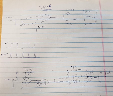
Now that we have converted our 50% duty cycle square wave into a pulse train based on the edges we can safely go back to the beginning and use one 555 timer since I know it can’t get stuck in the high state since the high state is generated by transitions. Since I still want the output to latch I’ll use the 555 in monostable mode and have some FETs to isolate the trigger and threshold pins. Now I think this is pretty slick and nicely compact. I’m done, right?

A coworker threw this up on the board and then left for the day. Ok. What am I supposed to do with this. Here’s my understanding about what’s going on. The capacitor blocks DC but lets the AC component of the signal through. What that means is it will generate a series of positive and negative going pulses (just like my differentiator idea above) and I don’t want those negative going pulses. The diode is (I think) supposed to snub the negative pulses. The capacitor and resistor are supposed to constitute a decay that is charged by the input pulses and drained by the resistor. The transistor obviously runs the relay coil when the capacitor is charged enough.

My stab at analog design still uses a FET as a switch
I’m not super comfortable with this level of analog circuit design, but I gave it a shot and this is what I found. The diode was drawn wrong, it should have been a series diode because as drawn the negative going pulses drain the second capacitor and no matter what components you choose at best you will get a 50% duty cycle output as the second half of the signal blows away any progress you made charging the cap. I solved this with a bridge rectifier so I could use both pulses (despite the forward voltage drop incurred). The last change I made was to use a FET instead of a BJT since I’m more comfortable with the capacative input of the FET not loading down the capacitor I’m trying to charge. I also found that you pretty much have to tune all aspects of this circuit together, the resistances and capacitances which makes it great for a single application, but not a universal design to be inserted other places unchanged. I think the dissimilarity in the pulses seen in the second picture are because if different forward voltage drops in my diodes, the tolerances are that tight on this one.

capacitor being kept charged, output being held low
drop the duty cycle and now it resets on missed pulses (doesn’t latch though)
After all that effort and iteration I realized some things:
- I need to detect edges, not states
- I don’t actually care if it’s both edges
I can detect on one edge because implicitly if there’s a second positive edge it implies the presence of a negative edge and the signal falling some time before it rises again, I just get the edges half as often. With this knowledge I can pick any number of off-the-shelf timers, I was just surprised that no one had a simple circuit to work on an arduino that detects both stuck high and low states. Hopefully this explanation gives some insight as to how you can easily build a hardware watchdog to suit your particular needs.
