For the one of you that has this blog as an RSS feed you’ll probably have figured out I’m not staggering posts, I put the information out there just as fast as I write it. I’m not looking to build a community, but more to be indexed on google so that people who are looking for help on specific subjects can get it.
This is a project that is a blatant rip-off… I mean derivative of a hack made by a friend of mine over at the i3Detroit hackerspace. His hack used the Wake On Lan feature to reset a server, mine could be used in the same way, but I tend to use it as a fancy lightswitch. That article I linked to has a fantastic description of component choice that I won’t try to duplicate here, I’ll just go over the implementation I used and how it differs from his.
I will first start by saying that this design has gremlins. It took me way longer to transpose the circuit from paper to breadboard and have it work, and I gave up trying to convert from breadboard to protoboard around attempt five or six and just started soldering components together and rolling up the breadboard circuit into a solder blob (which functions to this day). I have since designed a board for this project. I plan to eventually roll it into a tindie (or kickstarter kit campaign) but until I get around to that you can do it yourself with the provided schematic and eagle board files. Feel free to make a surface mount one as well if you feel that adds much benefit (it’s just a cost savings in board fab and parts, the size is already as small as needed (as small as the network card is).
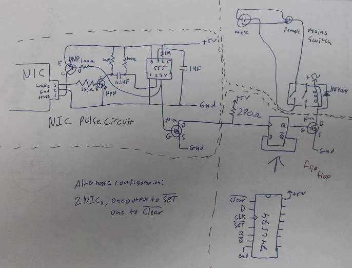
design document
My modification to the circuit uses the output pulse from the 555 timer to trigger the clock input of a D-latch (wired as a flip-flop) through a FET. Let that sink in for a minute, read it over a couple of times slowly. The last bit uses another FET to drive a relay based on the output of the flip-flop (a relay attached to the power strip).

breadboarded circuit
OK, so let’s start with the “through a FET” part. A Field-Effect Transistor is a transistor that has an amplification curve such that it is effectively an on/off switch. That means that while it is truly analog, if we use it right it can very easily be used to just pass whatever current you need with a small signal. In this case I’m using it as a buffer so the 555 timer chip doesn’t have to drive the flip-flop directly. This is overkill, but with the amount of trouble I had making this work in the first place I though it wise.
Now we’ll tackle the “D-latch wired as a flip-flop” part. So, this may be a well known configuration (and having a bachelor’s degree in EE now I should know that) but I came up with it independently of anyone else. The latch takes whatever is on the input and puts it on the output when the clock pin is twiddled (rising or falling edge, I’m not sure). The chip I chose has a complementary output, that means they have the opposite of the output on another pin, so when the output is at 5 volts, the complement is at 0 volts and vice-versa. I used this to my advantage. I wired the complement to the input so that whenever I clocked the chip the output would change to the opposite as I latched in the complement to the output.
The modification I suggest is that rather than oscillating the output you could have two network cards with two MAC addresses and when you WOL one it turns on the relay, and the other turns it off, regardless of the state beforehand.

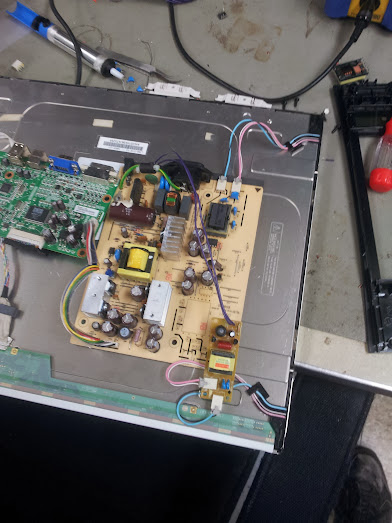
blobs that work so well
After this picture was taken I decided that having the neon lamp indicate status would be preferable because the one on the powerstrip sucked. The blob on the left is the 555 timer, the one in the middle is the latch, and the one on the right is the relay. The whole thing is built into a computer power supply body and powered off of a salvaged 5 volt wall-wart. The software I use is either wakeonlan for linux or any wake on lan client for android and I can blip the power from the internal network. If I can ssh into a server on the network from the outside then I can blip the powerstrip from anywhere on the internet. That is not really useful because there is a small chance of the circuit bouncing (an RC damper could help) and my current one doesn’t turn it off, it only changes the state.

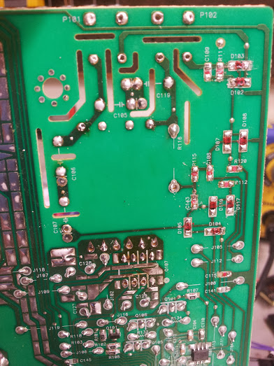
whole thing
There it is, a way to use up all those PCI network cards wasting space on your shelf. No code, COTS parts, and you can flip a bit on your network. This is essentially a network attached bit, get 16 (one for on and one for off) cards and you can have a very very slow 8-bit bus. Throw on two more for a strobe line and you could bit-bang a dot matrix printer on the network. The cool thing is that you can literally solder the input 8p8c (RJ45 to some of you) jacks in parallel since they’re passively receiving.
The eagle layouts will go up just as soon as I go home and upload them.
EDIT:
Eagle layouts are up now, I invite you to do better (because it only took me a night).

design for though hole component version