Archive for September, 2015

ESP8266 RTC and NTP

September 24, 2015

This one’s a doozy.  Maybe not to read, or write, but to code it was by far the most ‘fun’ so far.  My decisions at the time may have been lost to the sands of time, but I will try to capture them here as best I remember.  Let’s start with NTP.  NTP is very good for setting a clock, but it takes a call out to the network, and a response back along with a bunch of calculation you’ll see later to get a good time out of it.  NTP is not suitable for repeated hammering if you want to append a time to, say, a log file.  a Real-Time Clock is great for keeping time (just like your alarm clock) but not so great if you have to set it.  You could send an offset to move it up or back a certain number of minutes, hours, whatever if you need to set it, but we’re already on the network so why not do it automatically.  The code I write can work so much faster than I can and synchronizing clocks is not really something to be left to ‘eyeballing it’.

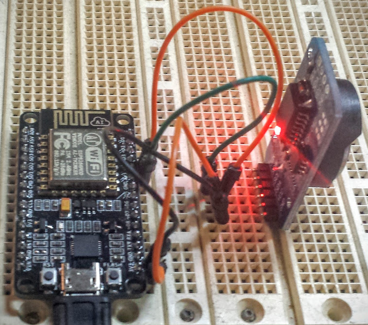
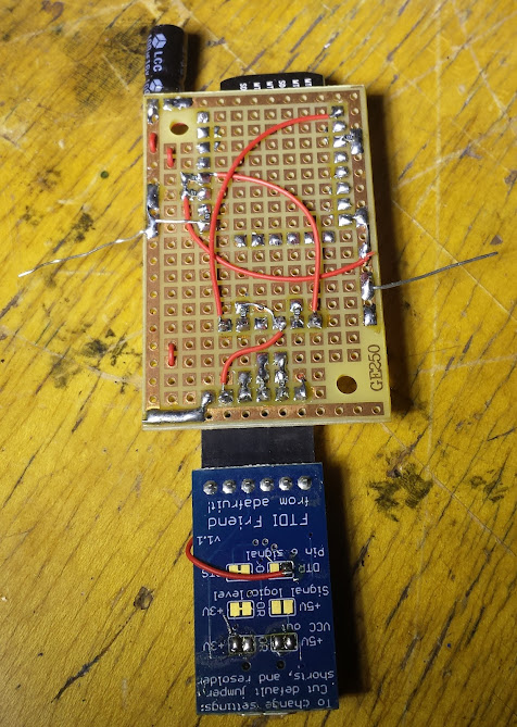
The most common RTC is the DS1307, it’s everywhere, like popcorn almost.  The chip I ended up using however was the DS3231.  In case you were wondering, the DS prefix is a holdover from when Dallas Semiconductor used to make them, they were bought by Maxim and that is where you can see new products coming from.  The DS3231 is more accurate, but most importantly for me is that it will run off of 3.3v.  You can see one of my favorite blogs go over how to use them here, my use case was getting it set by NTP, then using it to timestamp data.  The ESP is supposed to have an RTC in it, but it uses a pretty bad oscillator, even then I don’t know how to use it.  For this project I elected not to unravel the use of RTC libraries to write one for the ESP specifically and rather just use an off-the-shelf one.

The first challenge I had was getting the clock to read.  That code was taken blatantly from a library’s example and trimmed down to accommodate what I needed.  It included a bunch of checks to see if the time and date coming from the RTC made logical sense, which is useful when you’ve got a 50/50 chance you wired up sda and scl correctly.  I left in pretty much everything from that example and adapted the functions to be printed, printed to serial, to return a string, whatever was needed.  The code I provide isn’t that hard to follow if you view it in a way that allows you to collapse sections once you understand them (the code structure shows through more there).

With reading from the RTC done now I’ve got to read from NTP.  Another example to the rescue.  NTPClient had everything that was needed to get an NTP packet.  That’s not really all that useful, but the act of constructing the packet and getting it back successfully was done.  Now I have a packet (gotten from a straight UDP request) but the data in it is still Greek to me (actually I prefer to view things like that in HEX but…).  The final piece to the puzzle was on the arduino code repository (uh, oh! that’s never recent) and miraculously worked, but I needed to modify it for our application.  This was not designed for the ESP, so all the network initialization stuff had to go, substituted for our own.  Thank god for API standardization, because the wifiUDP works just like the ethernetUDP.  The sending of the NTP packet function was used wholesale (but the function call was moved so that it didn’t go every loop (I did pull apart an example program after all).

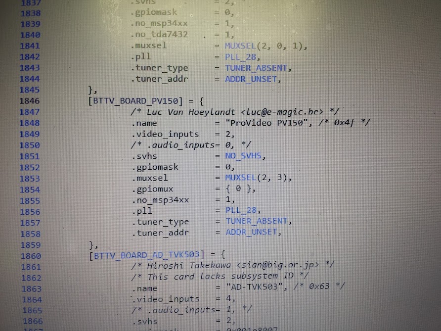
The code for converting from the NTP packet to a readable date/time value is complicated.  I found through experimentation that one version of the code wanted seconds from 1970 and the other wanted seconds from 2000.  I added line 284 (as of this version of the code) to compensate.  I also adjusted for DST since that was different as well.  The other functions I have in my code are really for formatting (and I’ve never made sprintf() do anything useful so I chucked it).  Now I have welded three different programs together using 3 different example programs to set the RTC from NTP.  After all that the rest seems trivial, but I’ll say that I have an update interval to set the RTC by and MQTT commands to request a timestamp or set the clock.  I didn’t put in the ability to set the update interval, but that’s also do-able.  This code, however terrible should really be broken out into a separate file so I can include it in many projects.  I like having time, now any output could be a clock.  If you really wanted to there’s a cron-like interface to use with arduino and you’ve got an alarm clock.  Some nixie tubes and shift registers would get you a very pretty one (even use a decatron for seconds).

As should be expected the code is here.

The rest of this series can be gotten through from the home page here.

ESP8266 Bistable Relay

September 24, 2015

As you can probably see, I’m putting together the building blocks to do something better.  Each of these articles describes one sensor and how I hooked it up to the ESP, but on their own these are not that useful.  This article is possibly most true in that department.  I have mentioned how much I like bistable relays before, and I mostly mention it to get more people to buy them because right now TE Connectivity seems to be the only people making them and I want tons of cheap ones out there to play with (there are breakouts on ebay, but seriously: more people need to love these things).  The benefit is simply that they are relaxed in two states.  There are/were ratcheting relays that have more relaxed states, or possibly move sequentially IIRC, but what I’m talking about are relays that can be light switches.  That means at least SPDT(3-way switch equivalent), and hopefully DPDT (n-way switch equivalent).  I may be using a power-hungry micro-controller, and not putting it to sleep, but dammit I will not burn current in a relay coil!

The problem with using a bistable relay as a light switch is that without sensing if the power is currently flowing you have no idea which way will turn the lights on or off.  If you remember which way the relay is currently settled you could do a ‘toggle’ to switch to the other position, but this does not help with ‘turn all the lights off’ unless you know which ones are on.  That method also takes a bit in memory because at any power up the relay could be in either position (you can read the state of a digital output to see if it is set high or low, but in this case that isn’t happening).  The answer I’m sure most people would come up with is to use a current sensor.  Either a non-invasive current transformer or a shunt resistor.  That is a fine idea, and there even exists a nice library for doing just that on the atmega 328, but I haven’t gotten around to porting that to the ESP yet.

The very clever method I saw once was to take a neon tube, a 100 ohm current limiting resistor and a photo-diode.  You wire up the resistor and neon tube to glow when the power is flowing to the light and detect it with the photo-diode, putting the whole thing in heatshrink.  This is a very simple opto-isolator, but it uses a neon tube to be compatible with high voltage.  There are detectors that can sense voltage and even digitize the frequency, but I would much rather have current reading so I’m holding out for that.  I may use the neon tube trick to get off the ground if I can’t port the current reading code fast enough, or I could throw on a 3.3v arduino pro mini and offload the analog to that.

The current implementation is just controlling a power strip with no feedback (look for the current reading or voltage detection in my power node post when I get that solved).  The relay takes the 3.3v signals and drives the coils through 2 2n7000 FETs, they’re very convenient and I’ll probably get a favorite smd one but for now I love these.  The relays are 5v coil, and get powered before the 3.3v regulator on the NodeMCU.  I have 2 pins, and while I call them On and Off, I labeled the relay with A, B, and C(ommon) so I wouldn’t forget what the pinout was (or which FET triggered what.  This setup’s limitations are that I cannot determine the state on boot, and cannot determine if it is flowing current or not.  I have listed how I could do that above, and even now I could have it switch Off on boot just in case it was on, but I haven’t.  The code assumes off on boot, but intil you trigger one of the coils that will not sync up with what the output is.

What I did for MQTT commands was to have the relay only triggered when needed.  I envision sending broadcast messages saying to turn off the lights and I didn’t want to fire the coil if it wasn’t needed.  This also allows me to keep track od the relay state so I can poll for it without changing it.  This, coupled with MyMQTT for android basically recreates the other networked power strip that I built before, but I have to be running a server for this to work.

As should be expected the code is here.

The rest of this series can be gotten through from the home page here.

ESP8266 Temp and Humidity sensor

September 24, 2015

One of the simplest things you can do is hook up a DHT11 to an ESP and get a remote temperature reading.  The fact it includes humidity too is a bonus, most people don’t go looking for humidity sensors nearly as much as temperature sensors.   The DHT11 is fine and all, but I happened to have a DHT22 handy.  The differences are minor, but the code needs to be updated.  There is a library to use these sensors with and it is quite handy as well as the example code calling out how the settings need to be changed in the comments.

My implementation has 2 MQTT calls, one for the temperature and one for the humidity.  I added a second output line to each that sends a message to the LED sign for display (although it’s easy enough to amend what topics these are listening on and what they send to).  Now when you ask for temperature or humidity you get the response to inTopic, but also it gets displayed on the sign.  You could have an architecture where the temp sensor is listening on a topic and the humidity is listening on another and when either get a message they interpert that as a command to send their reading out, but they pick the channel based on the message you send them.  You can also have delimiters and parse the commands pretty easily from one topic.  There  are so many ways to implement MQTT it’s both fantastic and terrible.  You can do it however works best for you, but anyone else’s system will need adapting to work with yours.

As should be expected the code is here.

The rest of this series can be gotten through from the home page here.

ESP8266 flow meters

September 24, 2015

Here, real quick is my implementation of two liquid glow meters on an MQTT enabled ESP.  I really was thinking about what in my house to instrument, but it always seems that I want everything to be automated, but it’s hard to decide what you’d do with the data once you put so much effort into getting it.  I figured I’d instrument the hot and cold water to look for leaks, and to watch my usage.  I may only need a tiny hot water heater, or I may be running it out fast.  Also, charting the time on of the hot faucet may give an indication to how much water is wasted staying cold in the pex.  Anyway, my data could be used to size upgrades or energy saving things for the house, and the whole thing cost less than $20 in quantity one, so why not.

I decided to go with a plastic flow meter I got from an ebay seller whose cart I was filling up to get free shipping (see, I use the fluff I pad with).  They happen to be the same as the plastic flowmeters adafruit stock, so that’s nice.  The sensor inside is essentially a waterwheel and hall-effect sensor that counts rotations.  The sensor says it operates from 5 to 18v, but I would rather it run at 3.3.  I elected to just run it at 5 because the sensor may be less responsive, or accurate if it even did anything at 3.3v.  The output is in pulses and the pulses are naturally 5 volts, which is a problem for me.  The best thing about uni-directional sensors is that the voltage divider is just a pair of resistors.  Put simply, the voltage drop across the resistors is going to be 5 volts, but you can pick where along the drop from 5 to 0 you want and get a lower voltage signal out.  This is what I did to take the inputs from both flow meters (12K and 22K resistors were used to good effect, I have heard problems with different values).  The total bill of materials for this project is 4 resistors, 2 sensors, and one NodeMCU (which can be changed to an esp-01 when it is done being developed).  I’d say that’s pretty cheap for network logging flow meters.

This time the code is relatively simple, but with one quirk: we’re using interrupts.  The code that adafruit provided uses the hardware registers on the arduino to set the interrupts but we use a simpler method, with the ESP you can simply say attachInterrupt(pin#, function, type).  In that statement the pin# is which pin should be used for sensing, function is the function that will be executed when the interrupt is detected, and type is whether it is on a low-to-high transition, high-to-low, or either.  With that, a local counter variable, and some math to convert to liters you can see just how many liters have flowed past the meter since you last checked.  This is a rather basic implementation to show the concept with just 2 MQTT commands to read the flow out, in a final version I would add an RTC to send updates periodically, another command to zero the count, and auto-zeroing on perhaps a daily basis after the data has been sent and acknowledged as recorded.

As should be expected the code is here.

The rest of this series can be gotten through from the home page here.

ESP8266 LED Display

September 23, 2015

This is my proof-of-concept for using mqtt with the esp8266.  I saw this LED display sitting around and I couldn’t imagine why no one was using it, the answer was no one knew how to talk to it.  Easy, I think.  Looking at the board it’s just an 8031, a serial level shifter, and a bunch of display-centric parts.  The pile of capacitors around the max232 equivalent was the give-away.  capacitors external to the chip are needed in the voltage boosting/negative voltage generation circuits for rs232 levels (until recently, I hear someone put them on-die).  Tracing those signals is easy and I found they went to UART pins on the 8031.

Assuming this chip is just listening for ASCII to be sent to it I started trying all the common baud rates… nothing.  OK, uncommon baud rates… nothing.  Maybe it’s some other parity, or stop bit encoding… nope.  It takes a while to run through all the permutations of rs232, and I did.  Now I’m thinking this takes some special character (or maybe CR/LF) to display a line.  Black-boxing that could be quite difficult.  Somehow, while hammering on the keyboard I saw something.  After trying every character from the ASCII table I came up with this list of printable characters: A-Z, 0-9, space, hyphen.  That’s it.  On a set of sixteen-segment displays.  Even the BOOT MESSAGE has lower case letters! Maybe there’s codes for some things but that’s what I finally gave up on determining.  I’ve settled for that subset of the ASCII set (at 4800, 8N1 if you care).

Serial connector added by me

Now we get to interfacing the ESP to this.  Really all I needed was the serial TX pin (actually I could probably use a software serial if it’s just transmitting at 4800 baud and not even listening, but I had a TX pin).  The signals for this sign are RS232 level, not ESP friendly.  I just patched in between the level shifter and the 8031 to get to the 5v level signals, much more microcontroller friendly (if someone says to just flip the polarity and let the rs232 driver at the other end sort it out, just say no!.  Luckily since the ESP only needs to transmit the level converter up to 5v is… nothing! That’s right, sending the 3.3v signal to the 5v chip is just fine.  Probably even in-spec.  Not that it matters since it works.  So now I have a way to talk to this sign from the ESP, but I want to stick it in a box and have it as a completed project unlike most of my hacking which is to write an interface for something and just let it be (never mind that I’m just making this interface to mqtt).

This is what I came up with.  It has an FTDI header, a 3.3v power regulator, and jumpers so I can pick where the signals go.  I don’t feel like typing this out so I’ll add the pictoral documentation (god bless white-board tables).

This allows me to set the ESP into program mode, connect the ftdi to the display so I can talk to it over usb directly, or connect the display back through the level shifter to the serial port.  that sounds like enough configuration to me.  Now it needs to go in a box.  Now I’ve got this breakout board soldered to a more edge-friendly one and the pinout looks like this:

So, along the side of the case I have a barrel jack for power, a DE-9 connector for RS232 level serial, and this layout of jumper positions and FTDI header.  All put together this makes for a pretty decent interface and I have been successful in connecting the FTDI friend (stock one, not my modified one) for programming of the module.  The completed box is transparent acrylic and was made using inkscape, boxmaker, and some custom holes for mounting.

The code for this is fairly simple.  I’m using the PubSubClient library to communicate over mqtt and I use the display for debug since, you know, it’s there.  Connecting the ESP to the wifi means you need an ssid and password (you could implement a clever hopper that looks for unsecured wireless and jumps on that, but I decided that for this I’m not going anywhere and would hardcode the ssid in.  I had it display whether or not it was connected to the wifi, then the IP address it got so I knew it was on (and the right network).  The code then publishes to OutTopic that it has connected (it actually says ‘hello world’ but for now that’s fine, it will change to a unique identifier when I get more of these devices.  It also subscribes to two topics, DisplayTopic and DelayTopic.  Both of those are used for changing the behavior of the sign.  Since this sign takes no input (not even a light level meter) it has no reason other than boot (or perhaps heartbeat) to send any signals out.

The code that handles the scrolling is actually pretty simple.  Since this is updating at 4800 baud the redraw rate is visible, and annoying.  I decided that since every character sent to this pushes the others off the end I’d take advantage of that and just push one character at a time and delay between them to have a given speed for scrolling.  anything sent on DelayTopic will get picked up by this sign and sent through atoi() to convert it to a number.  that number will be the number of milliseconds the program delays for between characters.  Because of this trick I can’t scroll the other way, that would involve redrawing the entire display and it looks terrible.

<Update: the following has been implemented, first try too!> The text interpretation is handled by simply padding with spaces to make the whole message at least 16 characters.  That doesn’t work however since if they are un-displayable the sign does nothing rather than inserting a space so you get smaller strings and artifacts.  The thing to do then is check to see if there is a valid character there and if not put something else there (I wasn’t quite truthful when I said it didn’t display other bits of the ASCII set, it does, but as garbage).  I think in the very near future I’ll put in a check and if the characters are not on the approved list then there will be a garbage character in place instead.

As should be expected the code is here.

The rest of this series can be gotten through from the home page here.

Intro to my ESP8266 adventures

September 23, 2015

Since the Arduino abstraction layer has been ported to the esp8266 I decided to get onboard and start using it for all the networking projects the arduino needs a helper to accomplish.  In short the esp8266 is a little 80Mhz 32bit microprocessor from Espressif that has built in wifi.  It’s a bit of a power hog, but other than needing chunky 3.3v power there’s really not many downsides.  The chip has a very small number of IO for those used to throwing a beagle bone or arduino mega at a problem, but being fast and having SPI or i2c means those can pretty easily be overcome.

esp8266_wide
ESP-01 module (first one people took to)

I’ve been wanting to do some home automation things for a while, and up until now I was adamant that I would run ethernet cables to wherever there needed to be sensors.  After actually trying to run power around my nice, old, heavy, plaster house I’ve found I’m not a fan of plasterwork.  I also found that even the cheapest things you can hook to ethernet are more expensive than one of these esp8266 modules (except maybe one).  There are many of these little modules out there (most using the designation esp-xx) and there are more every day.  All modules use the same chip and bootloader so any dev board could be reprpgrammed to use any code.  This means that when they start showing up in production devices that you can upload your own code to control someone else’s hardware as long as you find what pins go where.

NodeMCU_DEVKIT_1.0
NodeMCU 1.0, my board of choice

There are may ways to program the esp modules.  Lua is surprisingly popular (surprising to me) and done by the NodeMCU people.  Of course the official SDK uses C (there is, sigh, an open source version too).  There is Micro Python for the esp, but it seems very limited at this point.  I use Arduino because the library and community support for it is so easy to access.

I cribbed the part of the circuit from the NodeMCU that makes it not need buttons (resistors on underside)

My favorite (see link below and new article) board to develop on is the NodeMCU 1.0 (or V2) board, it has all the pins broken out, a nice power regulator that you can supply from USB, and a built in usb to serial converter on it.  The other thing they did was use the control lines of the usb-serial chip to hold the lines on the esp high or low as needed to program it.  I liked this behavior so much I copied that part of their schematic to my own board that takes an ftdi friend.  Unfortunately the two control lines it needs are both transmit lines and even adafruit’s ftdi friend doesn’t have solder jumpers for that so I cut a trace and bridged it myself.  My goal was to have something standards compatible and I just ended up inventing my own standard… D’oh.

The push that I needed to get going was from another blog I follow (actually probably from hackaday reposting something he did that prompted me to follow him directly).  He had been using mqtt as a transport protocol to network things together.  I like mqtt for a few reasons, not the least of which it is easy to set up on a pi.  I also like that OpenHAB has a hook for it, but seriously it has hooks for everything so that is probably going to be my main controller.  In the case you need a lot of I/O I would probably SPI/i2c slave an arduino mega and have my own transport protocol for that data (although in practice I usually use the UART SerialCommand library).  There is the ability to do it the other way around, slaving the esp to the arduino and using it as a wifi chip, but now that I’ve seen the esp in action the idea of using clunky AT commands does not appeal to me.

NodeMCU 0.9, not as breadboard friendly

There’s the layout, what my intentions are, and now come the projects.

LED Display (proof of concept)

LED Display (for i3Detroit)

Bistable relay

RTC (set by NTP)

Current sensor

Power node (integrates current reading and relay like the Ubiquiti stuff)

Flow meter (for reading water flow, hot and cold)

Sump Level (probably IR distance and potted in epoxy when done)

Temp and humidity sensor (probably an esp-01 and a dht-22)

Wall control panel v2

PIR motion sensor (same code as condensate pump alarm)

New favorite modules

Setting up a raspberry pi mqtt server to display the IP and hostname on a Nokia LCD

All my code for this stuff will be uploaded here, I already have some of these projects done and will change these listed projects to links once I’ve written the articles.

PV981A-16 mod for autodetection in linux

September 22, 2015

Recently I got my hands on a video capture card, it’s a ProVideo PV981A-16, but I didn’t know that at first.  The card uses 4 Fusion 878a (formerly bt878) PCI video capture cards and a PCI-E to PCI bus chip to give a maximum of 16 ‘simultaneous’ composite video inputs.  In linux there is a driver for the bt878 based cards, and it has quite a lot of options.  These chips were very widely used and the cards they went on had many varied feature sets.  The card has several composite inputs, audio inputs, and some gpio.  The gpio is present because frequently this chip is paired with a TV tuner which requires some digital lines to set the channel or other multiplexers in the audio/video path, or buffered and used for relay contacts or security sensors (like PIR).

Because of the great variety in these cards the driver does its best to autodetect what card is plugged in and set itself up accordingly.  The problem is that the card autodetects as a PV150 (may not be a real card).  When I probed the card I saw 4 chips with 2 inputs each instead of 4, and for quite a while I was scratching my head as to how I could enable the remaining inputs.

trying to use an un-enabled input on one of the tuners

The revelation came that this card was being detected wrong.  Well, not wrong, but the identification the card had was shared (presumably) by another card that only had a total of 8 inputs and it was being detected with those settings.

The ‘right way’ to fix this would be to add a definition in the bttv driver source for my card and have some way to detect it was the right card, but that’s not possible as the unique identifier that each tuner on this card uses is identical to a different card with different settings.  I could have tried to coerce the driver maintainers to accept that enabling more inputs does no harm except there would be virtual inputs with no actual connector for the card that doesn’t use them, but that also seemed hard and not very helpful to the community.  The way to test this would be to remove the driver module and restart it with a manual over-ride that picked a card out of the list that had the right settings.  I found the right settings by poking around in the driver source and finding another card that only differed in how many inputs it had (I knew the other settings worked).  The card I chose was BTTV_BOARD_GRANDTEC_MULTI which is card ID 77, or 0x4d (hex).

This card allowed it to fire right up with the right inputs and all 16 inputs could be detected.  The problem with this solution is that it is not portable.  If you remember from my keyboard adventures I prefer a hardware solution that can be plugged into any computer and work on autodetection rather than a bunch of software fixes that have to be applied after installation.  Looking carefully on the card you will see 4 socketed DIP-8 chips, there are also 2 data lines coming from each and going toward the 878 chips.  I checked and they are each 24c02 i2c eeprom chips, and at the end of their memory they contain hex strings that I recognized from the bttv source code.

This is how these cards are detected (for the most part).  Now I just had to look down the list of card identifiers and over-write these with ones that would detect as the right settings.  The Provideo PV143 seemed to have the right settings (and a similar bit pattern) so I went with it.

My trusty tl866 wrote these easily and now I have a card that autodetects incorrectly (it did before too) but with the right input settings.  I may have been able to just remove the chips and have it autodetect as generic/unknown and had it work, but this seems more resistant to driver autodetection changes in the future.

success!

I did my best to fill out the linuxtv page I linked at the top with all the information I was able to discern from the card (including gpio header pinout)  but it is still not complete.  I have an e-mail out to ProVideo asking for specs but I’m not very hopeful on that front.  After this adventure I feel like I could design one of these cards from scratch, or enable features that were never intended on other cards because they are so simple to use.  Don’t be afraid of the 878, go forth and hack!