Archive for the ‘new device’ Category

mini-sucker (gravity sucker)

February 5, 2017

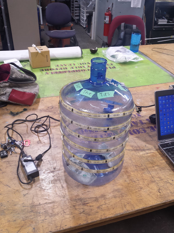
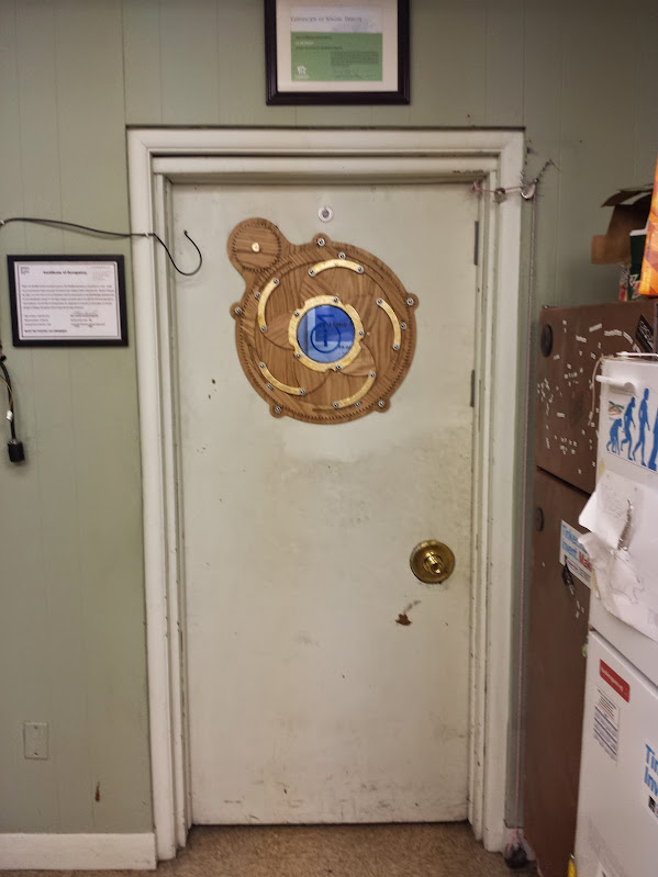
This past weekend (this post has been in the queue for a while…) there was the Ferndale Pig and Whiskey Festival.  I spend a lot of time at i3Detroit and was convinced to help out at this event. We have a large device aptly named the moneysucker as it consists mostly of a water cooler bottle, a shop-vac and a long tube.  That particular one is triggered by a non-contact mains switch and has a spiral of lights running up the tube.  Over the years that has been made sturdier and nicer, but now it’s hard to move and impossible to shrink without essentially breaking it and rebuilding it after.  The one I built is a sucker in name only; it is a water cooler jug, an arduino, a neopixel strip, and an IR presence sensor.

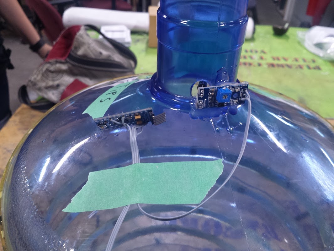
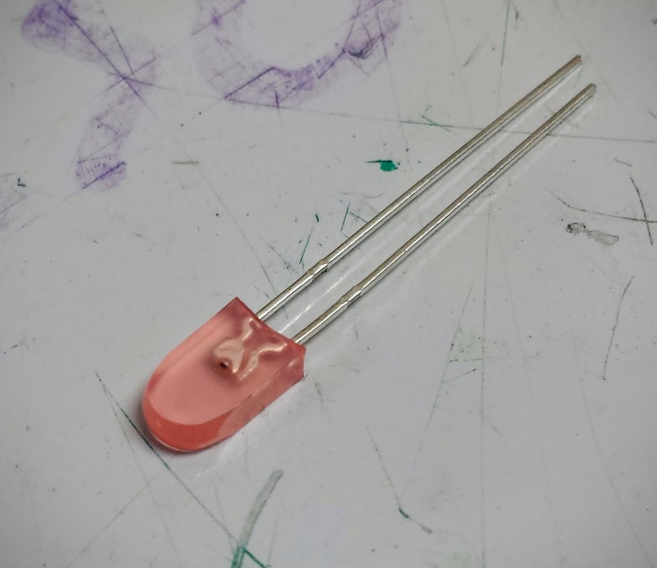
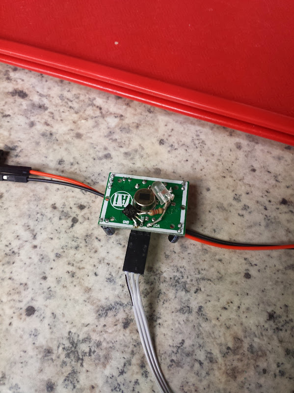
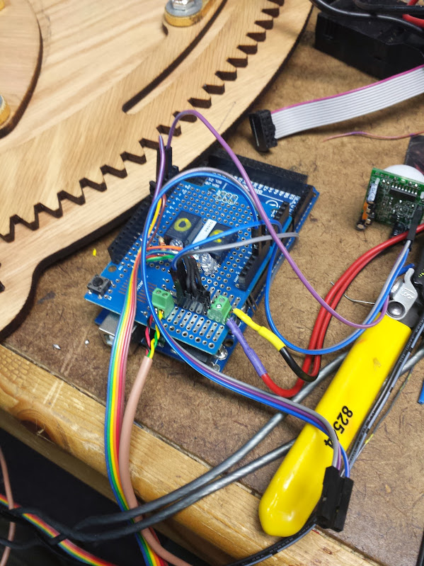
The first version I built used an arduino pro mini, but that died just as we were supposed to leave for the event.  My best guess is the little SOT23-5 linear regulator on the chinese knock-off board was not up to the task of stepping 12 volts down to 5 (even though I was not powering anything but the ir sensor and arduino with it).  The fix was to replace it with a full-size real-deal arduino, no expense was spared (although it wasn’t my expense).  The IR sensor had the LEDs pointed straight out, and I decided that I’d rather have them mounted at a right angle to make the board mounting easier.  That was a bit of a mistake.  Those LEDs are very sensitive.  All the sensor is is a comparator and a potentiometer to set the bias, so the level it triggers at can be set (theoretically a distance).  When I unmounted the LEDs the alignment became somewhat of an issue.  If I were to do it again I would convert the sensor to a beam break sensor, and heatshrink around the 5mm LED body to keep directionality.  This would invert my signal, but the pin change interrupt does not care.  The pin change interrupt is indifferent to your small mortal worries.

The code was a modified version of the adafruit strandtest.ino example expanded to the length of strip I was using.  I chose a default state I liked (the rainbow and rainbowCycle subroutines) and one I liked for the instance of having money inserted (theaterChase, white) and pulled out the rest of the calls.  The interrupt is triggered on a pin state change  so no mater what I use for a sensor (reflective, beam break, etc…) it will trigger a blinking state.  The theaterChase subroutine was also tweaked to be more intense and shorter.  The delay passed in the subroutine call was shortened from 50 to 20,  and the number of cycles was shortened to 3 instead of 10.

edit: now that I know someone actually plans to use my code I’ll reveal a secret.  There’s a bug.  It’s not major, and it only really shows up when you’re playing with it and not depositing money, but of course that’s when you’re showing off your new thing and you look stupid when it seems to immediately break.  If you fingerbang the jug fast enough then it will lock up in less than 20 seconds of doing this.  I think it’s because I used interrupts and while some people may sit smugly and say that’s the ‘right solution’ to this coding problem you need more knowledge about code than I do to use them properly.  If this were all my code it would be non-blocking without interrupts and check the pin state between each push of color changes and everything would be fine.

the code is here.

the rest of the pictures are here.

serialderp – completely non-autonomous arduino robot

August 11, 2016

This is an extension of the pervious robot, derpderp.  A friend wanted something to use for makerfaire Detroit to show off a bluetooth attached armband.  That sensor interfaces with python on a raspberry pi 3, and since I have some experience making python controlled robot platforms I volunteered to help.

The code I wrote just conflates the original derpderp code (which I use to drive the robot) with the wheelchair robot code that I use as a framework.  The additional things are setting the servo angle (what used to be the lidar platform), turning the light on and off (added to the lidar platform), and getting the temperature and humidity from an onboard sensor.  When making this change I found that the battery wasn’t working so I dug up the charger.  Then I found it wasn’t charging… so I tore apart the charger and bypassed the fuse.  It still wasn’t charging so I tore apart the battery and bypassed the fuse.  Then it finally worked, but that battery was so anemic anyway I decided to upgrade it.

The original battery was a 9.6v 500mAh battery, I replaced it with a lithium jump pack.  I had bought this jump pack for my car with an unreliable battery (which I eventually replaced) and somehow ended up running it over in my driveway.  I don’t even remember taking it out of my car and the next day it’s in pieces on the driveway.  After looking it over it still looks intact.  The plastic is shattered and the box that goes between the battery and the jumper cable clips has been crushed and the open frame relays inside will never function again.  That box, as far as I can tell, has a microcontroller in it that just supervises the closing of a bunch of little parallel relays to connect the care battery in parallel with the lithium pack (no protection whatsoever).  To me that means that I now have a connector and cable that will give me an unregulated voltage that I am glad to use for my motor power.  The charger board for the jump pack has a variable dc-dc on it to make different voltages, a usb port, and a flashlight.  I took the flashlight off and drove it at about 20mA with a resistor and a FET off the regulated 5V I’m making on the robot.  That’s the headlamp on the robot and it’s steerable with the servo as well as PWMable.  The control board is now only useful as a charger for the bare lithium pack as the battery voltage is not passed through it before hitting my robot.

The commands are:

sCmd.addCommand(“HUM”, humCMD); //no args

sCmd.addCommand(“LIGHT”, lightCMD); //0 – 255

sCmd.addCommand(“TEMP”, tempCMD); // if ‘1’ then F, if ‘0’ then C

sCmd.addCommand(“TURN”, turnCMD); // sets turn -1000 to 1000

sCmd.addCommand(“SPEED”, speedCMD); // sets speed -1000 to 1000

sCmd.addCommand(“ANGLE”, angleCMD); // sets angle of servo, 20 to 160

That’s a fairly easily controlled robot.  I don’t know exactly how the project went because I was on vacation for the week leading up to makerfaire, but there were some problems sending the commands from a raspberry pi (and I still don’t know why, it was over USB).

code is here.

pics are here.

autonomous version is here.

derpderp – Autonomous arduino-based robot

July 15, 2016

Here is yet another autonomous little robot that rolls around avoiding walls, this one was also made for a hackathon much like the venerable wheelchair robot.  The difference here is that insistence that code be developed on an SBC slowed development to the point that many features had to be dropped.  The point of this robot is to venture into unknown territory and send back sensor readings (distance, temperature, humidity, light level, barometric pressure) so you don’t have to go in blind.  The need for autonomy come from us not having a camera with which we could drive the robot.  The goals as best as I can remember:

  • autonomous exploring (drive forward, avoid walls)
  • wireless telemetry
  • large array of sensors
  • manual over-ride
  • make duck noises

The only things that got implemented out of these were the first two.  I put a lot of effort into making the only touchscreen we had (a SainSmart 2.8 inch TFT LCD) work as a UI for telemetry and control but was no able to make it work.  I still cannot even after buying the adapter for the arduino mega.  Usually I’m able to get around shitty documentation by digging through the code of the libraries, but this one beat me.

The large number of sensors… We had a BH1750 Digital Light Sensor, never got it to work.  We had a BMP180 Barometric Pressure/Temperature/Altitude Sensor, didn’t have time to make it work.  An HC-SR04 ultrasonic sensor, also never made it do anything.  A DHT22, the simplest sensor we could have installed… nope.  So, we had absolutely no sensor readings but it had a bunch of stuff plugged in so it looked impressive.

The actual navigation was done using a LIDAR Lite, which is a really cool i2c lidar sensor.  This was borrowed from a FIRST team and unfortunately no longer resides with the robot.  I thought about getting another one, but it’s just too expensive to put on a robot that I actually have no use for.  The chassis was the absolute biggest, most expensive RC car that walmart had to offer.. a New Bright 1:10 Radio Control Ford Raptor Truck, Black/Green.  No, I wasn’t much impressed either.  For a chassis this had loose ball joints, an anemic little lithium battery pack, and a motor that was rather poorly geared for torque.  But if the chassis was perfect then we’d have no fun accounting for it later.  The motor control comes from a Sparkfun Ludus Protoshield (which I got in a ding/dent deal and is not labeled like that on mine).  The control is just two-bit direction and a pwm line for speed.

Sparkfun ProtoCAT board

Being in the IEEE lab at MTU we had the advantage of a 3d printer.  They may have taken away the band saw and drill press because someone took off the safety switches and didn’t either restore them or hide them well enough, but we could still make small plastic parts over the course of several hours.  We made a bracket to hold the LIDAR to the servo and cut up a chunk of an old computer case to affix the servo to the chassis.  Now we had a chassis with enough sensor to let it move.  You may notice this is the exact same setup as the wheelchair robot with the exception that it’s smaller and much lower power.  When you have a hammer and all that…  It should not surprise you that the same person wrote the code for that as this one.

The wireless part was going to be a whole custom interface between two esp8266s to allow for touch-screen control and telemetry… Well, when it came right down to it I flashed the wonderful ESP-Bridge firmware to an esp8266 and clamped that onto the serial port of the arduino uno.  That worked for a very short while and then stopped.  I then replaced the esp8266, put a voltage divider on the rx pin, flashed it again and then it kept working… oops.  This theoretically gave manual control and some sensor data, but in fact it just gave updates from within the code.  That meant a constant stream of almost nonsense that looked pretty impressive to the lay-person.

The duck sounds were actually going to be quacks made by a speak-n-spell I found at goodwill, but hacking that never actually happened.  That may be an upcoming post, because using one of those for a speech synth has always been a plan of mine.

The battery was the same one that came with the RC car, a 500mah 9.6v lithium pack with charger.  Really anemic for this use but it worked for the little while we needed it to.  I upgraded that with a later revision.  The bus power is provided by a little 3A adjustable dc-dc regulator from ebay that got set to 5V and had the POT glued down.  This is much better than the linear regulator that would just dump 50% of the power from our tiny battery as heat.

The code is here

The pictures are here

the hackathon post is here

LED Cylon Painting

July 1, 2016

I was inspired by a large bag of red ‘tombstone’ LEDs to make a larson scanner. These LEDs are exactly 0.1″ across which makes them perfect to stack side by side on perf board to get an arbitrarily long bargraph (but in a nicer form factor). This was to be put in a box that originally held the receiver for an aftermarket wireless video game controller. I designed and actually fitted the circuitry in there first. The plan was to make that take serial commands (or serial over USB) and have it be an ROS peripheral for an AI, or natural language processor, or just a roomba with some attitude. Following this build I was watching an episode of Futurama called ‘The Honking’ which featured this distinguished gentleman:

The quote goes:

BENDER
That painting, the eyes are watching me!

[Farnsworth walks towards a portrait of Commodore LXIV.]

FARNSWORTH
Hmm. It has motor eye sensors attached to motion detectors.

BENDER
So does my butt, but I don’t frame it and put it on the wall! Although…

Then he got an idea. An awful idea. The Grinch got a wonderful, Awful idea… What if one of those paintings could follow you and was of a regal looking Cylon. I commissioned a friend at i3detroit to make the painting (a replica of a famous painting, but with a modified head/helmet) and got to work on getting someone else to help with the motion detection. Yeah, I farmed out the work but that’s because I like it here in embeded-land.

The openCV code to detect faces wasn’t hard, it came from a certain mustache example some of you may be familiar with. The painting turned out beautifully, and went to makerfaire. The problem was that the raspberry pi is not the fastest computer for video processing and the pi camera does not deal with changes in exposure well. The face tracking was a failure, but I hope to try that again in the future with a more powerful board.

The hardware is just shift registers, LEDs, and a pro mini. The code is simple, but it’s a good thing I put in an auto-scanner routine for operation without a computer. The manual control can set any LED position on, and then resume scrolling on command.

The code is here.

The pictures are here.

TTL POV globe redesign (part 1)

June 28, 2016

Back in college I built a POV globe.  I was really not happy with it, mostly because it’s something I felt could be done with discrete hardware more easily.  The first part to getting the POV globe in chips is to work out how to store the lines and retrieve them.

The big plan includes using a bigger chip with bank switching for animations and maybe even higher bank switching for going between animations.  This means that we need X address lines for 2^X lines, Y address lines for 2^Y frames, and Z addresses for 2^Z animations.  Eventually I would like to have a dynamic clock divider so we can have a variable speed motor and still scale the line frequency to keep the image all displayed in one revolution.  For now I have put together a clock out of a 555 timer, and decoders for the 28C64 EEPROM made from 74LS161 chips.  The EEPROM was programmed using the TL866 programmer to a sequential pattern as an example.  You can see that this chunk of the circuit iterates through the addresses and the outputs are tied to LEDs.

<video showing reset circuit>

<video showing addresses counting up>

<video showing changing the clock speed changing (blink pattern in the chip)>

Next time maybe I’ll have a dynamic clock divider circuit.

here is the code.

Door Iris

June 28, 2016

At i3Detroit we had a door (as seen it the scrolling, scaling web 2.0 bliss that is i3’s main page [just go to the wiki for important stuff]) that frequently got opened into groups of people standing by the front door.  The groups stand there because despite this door always having existed someone decided that a good bottleneck for people is right there, in the way.  Other hackerspaces have paperwork filled out elsewhere in their space, places where you can sit down even, but not us.  I chose not to solve the problem of people congregating because it didn’t seem interesting.  Instead the problem to be solved was that the door was a bit too opaque.  We could, of course, put a window in the door.  The issue was that the door worked fine most of the time as its old opaque self, and we really only needed a window then there were people on the other side of the door.  An on-demand window.  A mechanical iris for the door of course.

This idea and the plans to laser cut it were blatantly stolen form the internet.  I don’t remember where I got the file I ended up using to cut it out, but it is hosted on i3’s wiki here.  The thing that we added to that is a car window motor spline.  This particular spline comes from a motor used by a FIRST team some years ago.  To model it I just drew 2 concentric circles in inkscape, did some math to calculate the offset of the spline edges from the center, and traced it out.  I provide it here if you happen to have the same motors we had (I don’t remember what brand or model they were.

The PIR sensors are pretty standard, but I wanted to jazz them up a bit.  That, and it’s easier to debug if you can see what’s going on.  I was inspired by the ‘electric eye’ description in stories about old-school home automation and added a FET, resistor, and orange LED to light up the shell of the PIR sensor whenever the output is triggered.  Based on my knowledge of historical electronics I would guess that the ‘electric eye’ in those stories is a big freakin cadmium sulfide cell that they pass motor current through.  That being said, tuning one of those systems is no way to have a relaxing weekend if you have a deadline anytime soon.

So now we have sensors for people and an actuator for the door.  Now we need limit switches.  My preferred way of detecting the limits of this mechanism is to use limit switches.  You could use motor current, but that is likely to vary over the life of the motor, wire, solder joints, etc. You could implement a rolling boxcar filter to pick out where the current should be based on the assumption it will be changing slowly over time but that relies on good sturdy mechanical connections and not much slop.  It’s also much harder to program, and harder on the wooden gears needing to put stress on the whole system to know when to stop.  The key aspect of using limit switches instead of motor current is that it does not stop if you put your finger in it.  I am of the opinion that if you put your finger in it then you must not care about it enough and deserve what happens to you.  I have also intentionally put my finger in it and with the motor moving on 5 volt power it doesn’t hurt that much.  To address how to fix this (because if the motor does not reach the limit switch then it never stops) I made the code so the iris opens upon reboot.


With limit switches you can tell when you’re closed, you can tell when you’re all the way open, but you cannot detect an intermediate state.  This becomes more complicated when you talk about having two limit switches and two triggers on the same gear.  Because of how far the gear rotates to make a full movement of the mechanism it was not convenient to have one magnet and hall effect sensor.  I decided to add 2 sensors and two magnets.  This means that there is one position where the drive gear and ring gear can meet in order for the limit switches to work.  This gets tricky if anyone dis-assembles the mechanism and moves it by hand.

The only remaining question was how to power the motor.  It turns out that the motor that’s designed to run at 12V works great at 5V.  The problem with using a logic and motor power supply together is that when the motor browns out and resets the microcontroller you get a nice infinite loop of opening and closing.  A nice chunky power supply solves that problem.  We switched the motor with relays because the coil current draw isn’t an issue and dissipating the heat a FET would generate is also not how I like to spend a relaxing weekend.

<laser cutter porn>

The mechanical assembly was done with chrome 1/4-20 hardware, washers we lasercut out of a single thin sheet of polyester, coconut oiled wood (which we hastily cut on the wrong side, it’s not a symetrical design) and brass flat head wood screws.  The scale was wonderfully coincidental, we were given the porthole which had an ID of 7″.  When we scaled that to the whole project it turns out the 1/4-20 hardware worked great.  The porthole got a lasercut sheet of acrylic to replace the non-existent glass and a translucent ‘i3’ vinyl logo in the center.  The arms that move even got a real gold leaf treatment.  The mechanical build went smoothly and waited for a motor current based control board.  When that didn’t appear I put it into permanent install with my code and limit switches.

The code is supposed to do as follows:

10 open the iris

20 close the iris

30 if either of the sensor lines goes high

40     open the iris

50     stay open until 2 seconds after both sensor lines go low

60     close the iris

70 goto 30

It bounces around a bit and one of the sensor wires has fallen off inside the door (don’t use connectors when you can fit an iron in there, seriously) so it only opens from movement outside.  It’s not perfect, but it’s perfect enough that no one has been motivated to change it in the year and a half since we made it.

pictures and videos here.

code here.

custom arduino sound board and example

June 22, 2016

So, this is going to get strange if I’m blogging about things I’ve already blogged about.  I’m reaching pretty far back, but I think this is still new to the world.  A while back I designed some boards, which I know is very uncharacteristic of me but I did it and they worked fine.  I was surprised it worked the first time considering I took the schematic for the arduino pro mini, the adafruit wave shield, and a stripped down example circuit for the TPA3116D2DAP.  I’m going to say right now that this audio chip is just silly, especially for my design.  This chip can run in stereo or mono mode, and in mono and properly heatsunk it can drive 100W of power.  I am using it basically at the lowest end of the power curve, at 5 volts where my power supply sits and that puts out about 3 or 4 watts of power.  If I was using about 12 volts it’s be a lot more efficient, but I really don’t care that much about efficiency.  Prototyping that chip was fun, and in the end I looked at the example circuit for the output and figured that since I didn’t stock any inductors they must not be all that important and I omitted them.  Whether or not you agree with the logic, the circuit worked beautifully.  To solder it to a board I put a square of 9 vias and used it as a heat transfer pipe to melt the solder on the power dissipation/ground pad on the bottom of the chip (all you need is a pencil iron, it can solder anything if you’ve got the finesse).

Building your own power amp with these chips is really easy and I highly recommend them in new designs.  Given that my debate was over how to match the power of an lm386 at 9v with a different audio amp at 5v I think I succeeded.  The rest of the board layout went well.  I used a full size SD slot because it’s easier to get full to micro adapters than the other way around.  I broke out all the pins in a square around the package since I didn’t want to bother with the arduino pinout.  The FTDI header is upside down because it was easier to wire that way, there was no provision made for the height of the capacitors but they lay flat just fine, and the switch footprint doesn’t match because I didn’t trust the measurements the manufacturer gave and didn’t have time to get them here to measure myself.  All that being said, the boards worked beautifully the second time.  The first time I found that I got the atmega328 not the atmega328p.  Basically it means that you have to either rewrite the definition to include this fact or run -F in your avrdude command.  I copied the pro mini config file and tweaked one value to create a new board definition.

The wave shield and library are a little… primitive.  Don’t get me wrong, it’s fantastic but it basically hasn’t changed since the arduino was through-hole.  The whole thing relies on just moving chunks of WAV file to the ADC at a regular rate set by the interrupts.  There’s basically no more smarts to it than that.  This means a low part count, very common parts, and editing the library is easy for newbies to coding.

In addition to this  I added a lipo charger (which does not work if you attempt to charge and use it at the same time, from the same source, without diodes) and a lipo fuel gauge.  The fuel gauge may just be a watchdog that monitors the voltage but it’s easier than writing the algorithm myself.  Now I’m up to: arduino, SD input, amplified sound output, battery, charger, monitor.  That’s a pretty self-contained system.  Now on to the tasks I can preform!

The plan was to make the elevator make a sound when moving.  tapping into it wouldn’t be an option because this was actually entered in a hackathon in college and telling them I did that wouldn’t go over well.  I tried discretised integration, I can’t sample fast enough to make an integrator that doesn’t drift.  I thought about using an analog accelerometer and op-amps but I didn’t have any and then I’d be tuning drift with trimpots instead of #defines.  I could also design a completely analog self-zeroing system but I’m lazy and didn’t have the parts at the time.  What I did was implement acceleration bump sensor.  I’d sense a blip either up or down and assume I was in motion for the rest of the time until I felt a bump in the other direction.  This works except I make too many assumptions about how long and intense the bump will be.  There’s play in the elevators I used so jumping on the elevator without it moving is enough to set it off.  I did, however tune it so that with no overly strong exceptions it would work consistently.  I think a gyro would have made this more robust but, say it with me: I didn’t have one at the time.  It’s easy to implement something if you have all the right parts, the challenge is in the hack.

Here’s the video

Here’s the code

Here’s the board

Here’s the pictures


standalone heated bed controller

June 21, 2016

Back in the day when I was at college we had a RapMan 3d printer.  Do not buy this printer.  The version we had was flat-pack, made entirely of acrylic sheets sandwiching smooth rods for construction.  Staying up all night to get the first print got us a small ABS plastic cup and a rain of nuts, washers, and bolts.  If you tighten anything down enough to not shake itself apart you shatter the acrylic, and the controller is proprietary, so there’s not much you can do to it from that front.  We spent the first few weeks designing and printing replacement parts for the printer out of ABS because the acrylic was garbage.  The extruders were nice, but used a custom machined razor sharp worm gear that would just chew up material if it was too soft.  On top of all that, it didn’t have a heated bed.  If you’ve ever 3d printed something you’ll know that a heated bed is quite nice and helpful to get good looking parts.  Since we couldn’t interface with the damn proprietary controller we just built a stand-alone one.

We built this in one night, and to my knowledge it never got changed.  This is both a blessing and a curse.  If you half-ass something and it works ‘well enough’ people are not motivated to make a better one, this could mean even more time before you have a reasonable solution to the problem.  If the solution is truly good enough then it’s not an issue, but there’s a spectrum… The other thing worth noting is if someone decided to take a ‘good enough’ solution out of order and replace it with an un-finished ‘right way’ solution taking the functionality from 60% straight down to 0%.  These sorts of ‘fixes’ are the hardest to come back from because it involves either finishing someone else’s project, starting over, or putting back the first solution.  I would tend to lean toward the latter of these options, but that’s not always possible if the parts have been cannibalized in the course of making the whole system non-functional.

Being built in one night it used what we had lying around, in this case an original msp430 launchpad.  These had a bunch of features, plenty of reasons to like them, and most importantly an arduino abstraction layer ported to them.  Arduino may have a bad IDE with very few features and a convoluted system of adding boards and other support, but the important part is that it’s easy enough to get working fast and has enough of a community that making your first few projects work is super easy.  At the time when I documented projects it was on the IEEE Lab Wiki, considering that’s who it was built for and where people would look for documentation on how to use it.  These days I’m going through my google photos looking for something to document, not to bulk out the number of blog entries I have, but just to put together a repository of my knowledge.  I’m not planning on getting hit by a bus soon, but I bought my own house and am already not that healthy of a person.  Here is the excerpt from the wiki article I wrote:

Overview

The heated bed was purchased to increase the quality of 3d prints on the Rap Man. It is constructed from a bed from RepRapDiscount, borosilicate glass from Lulzbot and our own custom controller built from an MSP430g2553.

Specifications

Maximum Build Dimensions

  • X: 214mm (~8.5″)
  • Y: 200mm (~8″)
  • Max Temperature: 110°C (230°F)
  • Power Requirements: 12V @ 8.5A

Design

We wanted to use one of our launchpad MSP430s, but we wanted to do it fast, so rather than learn how to use TI’s IDE (we tried, there were major problems that varied between chips) we used Energia. Using some KEM-5161BR (common anode) 7-segments driven by 2 74HC595N shift registers. To conserve pins we configured the 8th bit on the second shift register to control the third 7-segment as either blank or display a “1”. We have the POT being read on one pin and the thermistor set up as a voltage divider on another pin. The FET (2 in parallel since we needed more current) hooked up to a digital output. The code is [[1]here].

Future Modifications

  • Replace the thermistor table with a function
  • Replace the on/off functionality with a PID controlled PWM
  • Move the FETs to a separate board (or further away from the pot
  • Replace the FETs with one rated for the current
  • Print a PCB


I’m actually not going to elaborate on that because I don’t remember anything else about the design, construction, or functionality. Looking back, my favorite part of the code is the comment “fitted graphically”, I think I’ll use that at work some time as justification for data.  On the subject of ‘future modifications’ I’m pretty sure none of that ever happened, although at least one person got burned by the FET (that really should have been a relay, way higher power with basically no heat).  This article’s ‘value add’ can be my story and perspective on the whole situation I guess.

pictures are hosted here

code (and an unbuilt board design?) is here

original wiki article for the lab is here

car compass (fail)

June 19, 2016

So, recently I quit my old job at Eaton and started a new job at GM.  Both automotive companies, neither really much different from each other and my part in them also not supper different.  That’s not important right now.  What is important is that I can get a better parking spot by having a GM vehicle (not entirely true, but I’ll go into that later).  I took this as the time to upgrade from my 2000 explorer eddie bauer edition with the most anemic engine and slushbox offered in that year, but all the bells and whistles to a 2003 saturn l200 with no options at all as far as I can tell.  This bumped my fuel economy from about 12mpg (as read by the green VFD in the explorer’s center console computer thing) to near 22mpg (as calculated by me keeping a spreadsheet of the fill ups I make in the saturn because I’m a nerd).  I also lost all the cool options I had, sun roof, power heated seats, cd changer, trip computer, and best of all: compass.  Some people may take for granted their old heap with all the options that’s worth about $800 had a compass and that any newer car will, but that’s not the case.  My new car didn’t (along with holes in the exhaust, a plate glass driver’s mirror, no hood release cable, broken windshield, and a really shitty radio) so I decided to add one.

When I’m driving around the most useful thing I can have to navigate is a compass, since this is Michigan (could you tell since I moved from one car related company to another) the clouds cover the sun and stars most of the time so I can’t use celestial navigation as much as I might want to.  If I’m in a subdivision that has lots of turns it helps to know which direction I’m pointing when I choose my route, or even when I’m on a main road that’s not a mile road, or one that intersects not at a right angle (I know, madness).  I have an IMU, I have an arduino, I have a display, how hard could it be?

The IMU I used is the mpu9250, a very popular one with enthusiasts interested in quadcopters, balancing robots, VR controls, whatever.  By picking a popular one I could use a nice library written by someone else.  That library even has optimizations for the teensy 3, which is cool.  I based my code off the teensy 3 example code but removed all the display code and substituted my own.  You may recognize my old code from this display I salvaged back in the day.  The cool thing about this IMU is that it also includes a temperature sensor which I can use. That gives me a total of X, Y, Z acceleration, gyroscope, and magnetometer as well as a thermometer all using only 2 pins!

Some of you may not recognize how useful a thermometer that updates live can be on a vehicle, let me disabuse you of that notion right now.  For some of you, the temperature outside your car may not change significantly from when you get in and start driving until you get out at your destination, but that is not always the case for me.  When you drive straight north for four hours in Michigan in winter you can go from slush, to ice, and back again several times which is nice to know considering that while you may be a consistent temperature and humidity in your seat the tires that keep you on the road are not so lucky.  That being said for my revision 1 I chose to put the sensor inside the cabin because I know from experience pushing i^2c over long distances near noisy electronics is a recipe for failure.

I also added a potentiometer and am reading that in a loop and mapping it to the brightness levels of the display.  I thought about trying to tie into the dimmer circuit in the car, but for now what I have is a stand alone device that I can velcro to the dash.  Should I want to integrate it into the vehicle wiring all I would have to do is adapt the dimmer signal from 0-12V to 0-3.3V and I’m done, the code’s already written.

That’s where this project stands, It’s a small self contained compass with temperature reading capabilities (limited range, but whatever).  I will also note that this does not work in my car.  This may not work in any car except this one but there is still a hope.  I originally stopped here when I got this working and realized that it had the exact same issue as a friend’s laser/radar scanner (in that it always read north east).  I was subsequently informed that certain aftermarket products have a calibration mode where you are instructed to circle clockwise and counterclockwise in a parking lot to establish ranges.  I know nothing about this calibration routine, but I should be able to figure it out some time soon.  As it stands this is a fail, but I use it as a thermometer in my bedroom since it’s just powered by a usb port.

My code is here

Additional images can be found here

Wake-On-Lan Powerstrip

January 20, 2014

For the one of you that has this blog as an RSS feed you’ll probably have figured out I’m not staggering posts, I put the information out there just as fast as I write it.  I’m not looking to build a community, but more to be indexed on google so that people who are looking for help on specific subjects can get it.

This is a project that is a blatant rip-off… I mean derivative of a hack made by a friend of mine over at the i3Detroit hackerspace. His hack used the Wake On Lan feature to reset a server, mine could be used in the same way, but I tend to use it as a fancy lightswitch.  That article I linked to has a fantastic description of component choice that I won’t try to duplicate here, I’ll just go over the implementation I used and how it differs from his.

I will first start by saying that this design has gremlins.  It took me way longer to transpose the circuit from paper to breadboard and have it work, and I gave up trying to convert from breadboard to protoboard around attempt five or six and just started soldering components together and rolling up the breadboard circuit into a solder blob (which functions to this day).  I have since designed a board for this project.  I plan to eventually roll it into a tindie (or kickstarter kit campaign) but until I get around to that you can do it yourself with the provided schematic and eagle board files.  Feel free to make a surface mount one as well if you feel that adds much benefit (it’s just a cost savings in board fab and parts, the size is already as small as needed (as small as the network card is).

design document

My modification to the circuit uses the output pulse from the 555 timer to trigger the clock input of a D-latch (wired as a flip-flop) through a FET.  Let that sink in for a minute, read it over a couple of times slowly.  The last bit uses another FET to drive a relay based on the output of the flip-flop (a relay attached to the power strip).

breadboarded circuit

OK, so let’s start with the “through a FET” part.  A Field-Effect Transistor is a transistor that has an amplification curve such that it is effectively an on/off switch.  That means that while it is truly analog, if we use it right it can very easily be used to just pass whatever current you need with a small signal.  In this case I’m using it as a buffer so the 555 timer chip doesn’t have to drive the flip-flop directly.  This is overkill, but with the amount of trouble I had making this work in the first place I though it wise.

Now we’ll tackle the “D-latch wired as a flip-flop” part.  So, this may be a well known configuration (and having a bachelor’s degree in EE now I should know that) but I came up with it independently of anyone else.  The latch takes whatever is on the input and puts it on the output when the clock pin is twiddled (rising or falling edge, I’m not sure).  The chip I chose has a complementary output, that means they have the opposite of the output on another pin, so when the output is at 5 volts, the complement is at 0 volts and vice-versa.  I used this to my advantage.  I wired the complement to the input so that whenever I clocked the chip the output would change to the opposite as I latched in the complement to the output.

The modification I suggest is that rather than oscillating the output you could have two network cards with two MAC addresses and when you WOL one it turns on the relay, and the other turns it off, regardless of the state beforehand.

blobs that work so well

After this picture was taken I decided that having the neon lamp indicate status would be preferable because the one on the powerstrip sucked.  The blob on the left is the 555 timer, the one in the middle is the latch, and the one on the right is the relay.  The whole thing is built into a computer power supply body and powered off of a salvaged 5 volt wall-wart.  The software I use is either wakeonlan for linux or any wake on lan client for android and I can blip the power from the internal network.  If I can ssh into a server on the network from the outside then I can blip the powerstrip from anywhere on the internet.  That is not really useful because there is a small chance of the circuit bouncing (an RC damper could help) and my current one doesn’t turn it off, it only changes the state.

whole thing

There it is, a way to use up all those PCI network cards wasting space on your shelf.  No code, COTS parts, and you can flip a bit on your network.  This is essentially a network attached bit, get 16 (one for on and one for off) cards and you can have a very very slow 8-bit bus.  Throw on two more for a strobe line and you could bit-bang a dot matrix printer on the network.  The cool thing is that you can literally solder the input 8p8c (RJ45 to some of you) jacks in parallel since they’re passively receiving.

The eagle layouts will go up just as soon as I go home and upload them.

EDIT:

Eagle layouts are up now, I invite you to do better (because it only took me a night).

design for though hole component version