Archive for the ‘interface’ Category

Star Trek control panel

February 5, 2017

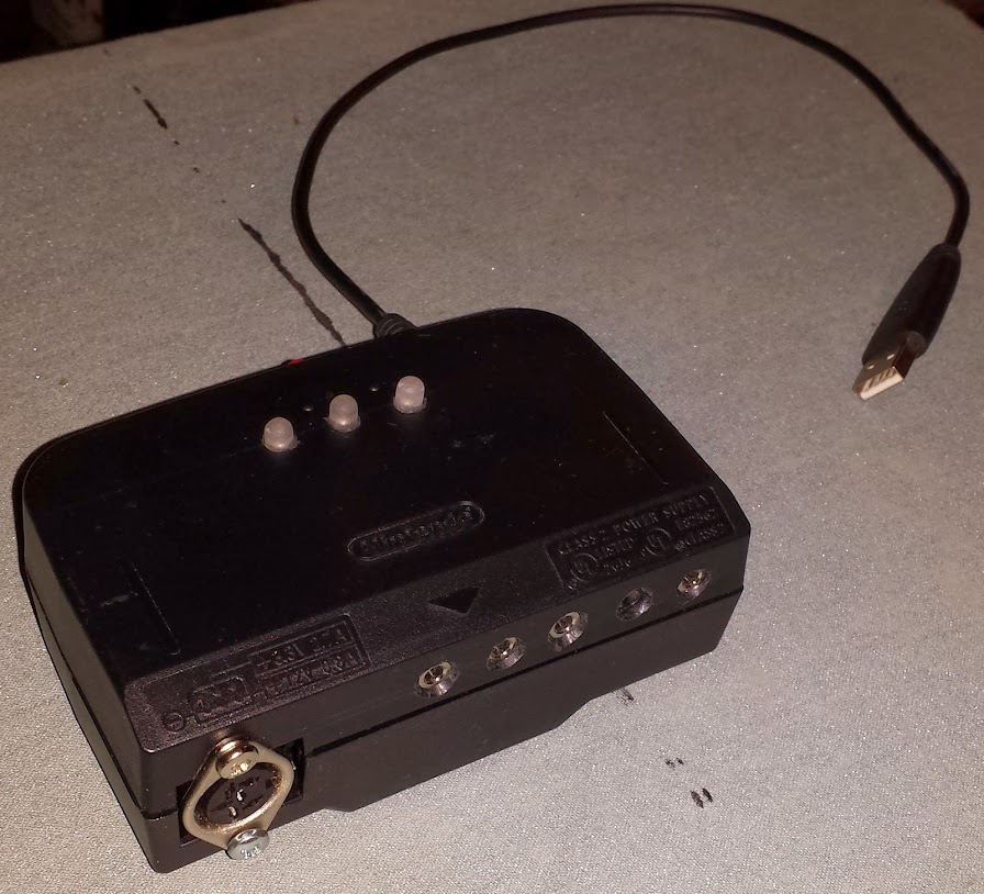
This is one of those things that starts out as ridiculous but just might work.  We’re putting in a door at our hackerspace, a pocket door, so obviously it has to be pneumatic.  I was asked how to control this door, and I had one answer: Star Trek Electronic Door Chime Think Geek wants $30, Ebay wants $28, the cheapest is Amazon at $25 and free shipping.  I ordered one right away with the intention of converting it for use as our door controller.

looks unmolested, doesn’t it?

I knew I would have to do three things:

  1. make the sounds triggerable on command
  2. take the inputs from the button and switch separate from their original use
  3. control that LED
  4. (optional) do something cool with that translucent bit at the top, maybe an RGB LED?

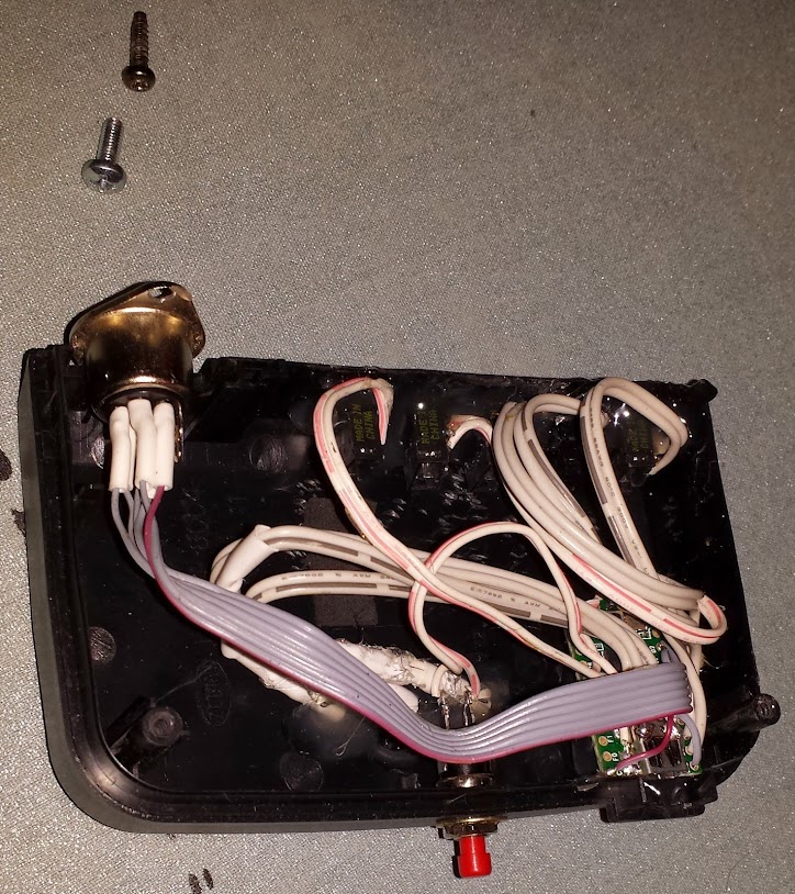
Let’s investigate the guts.

brb learning kicad

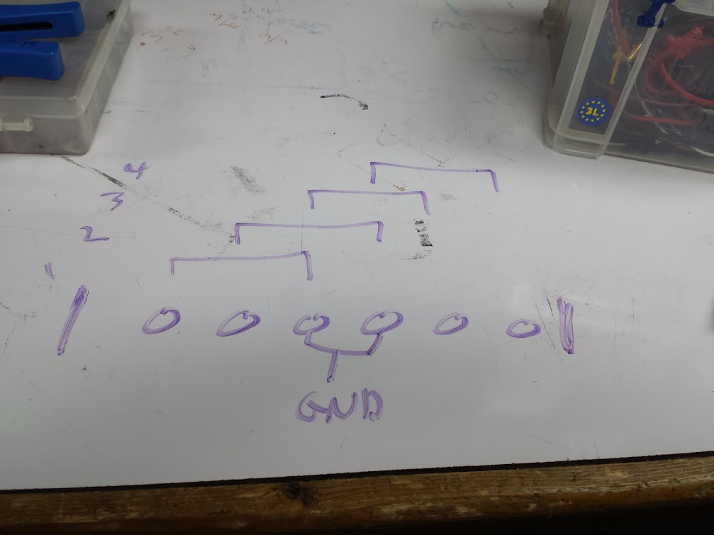
Unfortunately I did not take a picture before tearing into it, so here’s my recreation.  Top left, board with a single LED.  Below that is a board with a single membrane switch and that passes through the LED wires.  To the far left are two PIR sensors.  Out the bottom is the connection to the battery box. The right side has the speaker and volume switch.  The top right has the front slider switch.  The middle of the board has the switch to select which PIR sensor will activate the sound.

I didn’t really go into this with a plan, but step by step I made this sound board sing and dance.  The first thing was to pin out the PIR sensors:

didn’t use their own copper traces….

PIR sensors:
s1=blue=common
d1=orange=normally open (3.61v)
g1=green=normally closed (0v)
s2=white=common
d2=purple=normally open (3.61v)
g2=grey=normally closed (0v)

That’s that.  I found that I could replace one with a microswitch and activate the circuit, perfect! I had to tweak the timings once I got it hooked into the microcontroller but I could control them digitally, good enough!

not PIR, this is the new microswitch

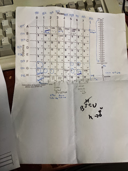
Next was the front switch board:

switch board
7=0v
up=woosh
7-8
center=none
7-9
bottom=red alert
7-10

That’s fortunate, there’s one common and three different things to be pulled down in succession.  I decided to use the trick of defining a pin as an input to make it floating, which worked great.  For inputs I used three separate pins with pullups to detect which was being pulled low.

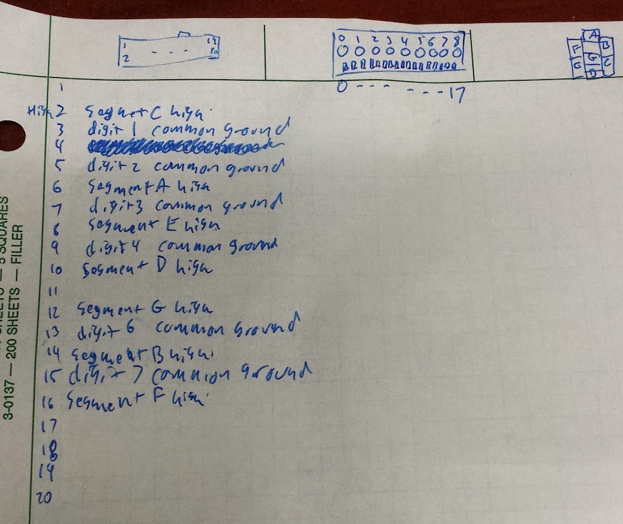
Last was the LED and button boards:

LED board
1=led positive (4.4v, floating battery)
2=led ground (current limiting resistor inline, switched)
resistor removed and shorted over

button board
1 – 6
2 – 3
4 – 5 button
5=4.38v (floating input)
4=0v

The decode here is that the LED gets tied high, there is a SMT resistor on the main board, and the ground is switched.  The button is on pin 5 and pin 4 is ground, so all I have to do is pull that low to activate it with a microcontroller.  I really don’t like how that LED is wired so I removed the resistor on the board, jumpered over it, and wired the switched pin (3 on the board) to an input on the microcontroller (pulled up).  I then wired the LED to ground and one of my GPIO through a 100 ohm resistor I added.  The button also got wired to me as an input.

Here’s the story so far:

Outputs:

  1. LED
  2. simulate front switch
  3. simulate front button
  4. simulate PIR sensor

Inputs:

  1. sound board output for LED
  2. front switch
  3. front button
  4. extra button from me (to trigger as if it was a PIR sensor)

power circuit

In this configuration I could essentially man-in-the-middle the entire board, but I had one limitation.  The red alert is supposed to be a burglar alarm for a cubicle (just like the hail is supposed to be a doorbell) and thus cannot be stopped mid cycle.  I decided the best way to fix this was to wire a couple of transistors so that I could drop power to the whole board and thus kill any sound mid-play.  This is a very crude solution, but seeing as my music box is literally 2 epoxy blob chips, I’m going to just call this good enough as well.

The jumper near the label R19 is mine (for that resistor I removed) and the pin the PIR chip out put is actually pin 2, right under that white dot

Now I have even more control over the board than I did to start with, I have written code that would simulate an unmodified board (no PIR though) and augment it with the ability to interrupt the sound being played.  If you really really wanted to you could take the PIR sensor in as analog and output it as PWM and maybe it would work.  I didn’t bother because this device has 2 PIR sensors and a switch on the back to choose between left, right, or both to activate the sound.  If you want a PIR sensor, just leave one in and connect the arduino in place of the other.  You can even switch between them to preserve as much original functionality as possible.

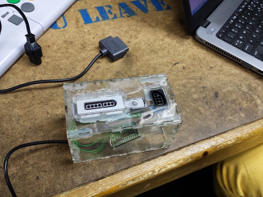
as wired in final assemble

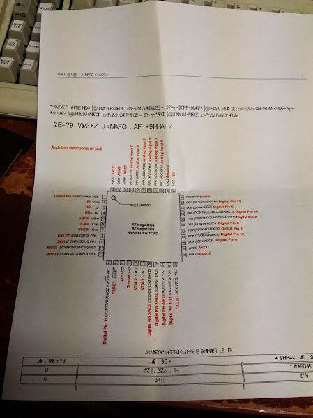
Somewhere along the line I thought I broke my code for simulating the PIR sensor (spoiler: don’t #define the same variable twice and expect it to work).  My remedy for this was to look into the TM2291 chip connected to the horrorshow of capacitors and resistors.  This chip turned out to be a dedicated PIR sensor reader chip.  Most of you won’t have ever dealt with this because you but modules that have something that does this onboard, but this device had 2 PIR sensors MUXed into one driver chip… I did not want to decode that.  I found an example circuit and picked the pin I thought must be the output to the sound chip.  After I desoldered the chip and connected in place of it everything worked (no it didn’t. but it was around this time I found my code bug).  Now I could also be rid of that switch on the back of the PCB.

polarity marked, it’s important

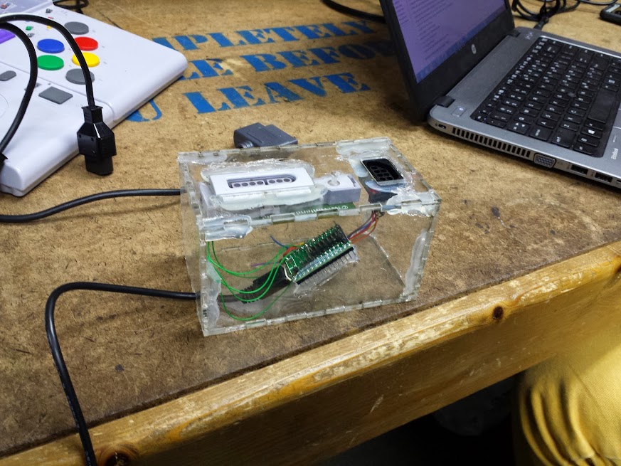
With the switch desoldered I had room to just about fit my FTDI header out the back.  One important thing: the RAW and the Vin on the FTDI header are not as connected as you might think, which led to some head scratching from me.  Here is the final layout as I have it now.

kicad’s going slowly

The diode is so the batteries don’t get charged from the ftdi header (but it can still power the unit).  The switch at the top is mine for triggering things instead of the PIR (glued where the PIR was).  You can see the NPN/PNP circuit I mentioned before to kill power to the board (and the power for that coming from the FTDI input, not any other pin on the pro mini).  The LED has a new resistor, and the button boards now go to the pro mini.  The arduino has a bunch of control lines running to the original board, but the volume switch was left alone.  This literally shorts out a series resistor with the speaker, I didn’t think it was important to make that variable.  You can see how I now have central control of all the inputs and outputs, which was the plan all along.

removed parts (and all the shitty wire)

The code I think this will be running in production is the command based one I uploaded here.  It’s overly modularized, but it works well.  Another hint: 8Mhz does not divide equally to give close enough to 115200 baud for input, even though the output comes through readable.  That’s a fuckin’ pain to diagnose.  I used 9600 this one time, as you can see.  My functions:

WOOSH does exactly that, plays that sound.
ALERT does the same as WOOSH, except it will be left in alert mode so the LED will blink
HAIL plays the hail sound
NONE sets the virtual switch to no sound, but can be used to cancel the blinking without playing a sound
KILL kills the current playing audio
ON turns the LED on
OFF turns the LED off
PASS passes through the LED state from the board, useful in alert standby mode or to see the blinking while playing the red alert sound
BLINK sets the board to red alert mode, does not trigger sound, LED blinks slowly
SWITCH returns the state of the front switch (0, 1, or 2)

The button on the front and the new button on the side asynchronously send 3 or 4 out serial, but they are debounced and only do it once per press.

That square board is mounted 180* off, and I cut the post/glued in the speaker to accommodate it.  Completely un-needed.

That’s it, I’m done, it works.  I anticipate this (maybe two) being serially linked to an ESP8266 (it wants 4.5 to 5v power, but 3.3v serial is fine) which will run the solenoids, read pressures, and talk MQTT.  If I’m really hurting for pins I can make the second one respond to different commands, make it talk different numbers, and hook them in parallel with a couple diodes, but that’s silly…

the code is here.

the rest of the pictures are here.

2.4Ghz analog camera scanner

June 29, 2016

This story has a part ‘back in the day’ and a part just a couple months ago.  Let’s start with the most recent part.  I decided that I want cameras around my house.  I didn’t say in my house, I said around my house.  I would like to be able to see my front yard, back yard, driveway, and maybe even down the street a bit.  I want cameras inside, but this is absolutely not the way to do it.  I came by a number of analog cameras with 2.4ghz transmitters, but the receiver I had used analog tuning.  I never worked out whether it would pick up all 4 channels of camera (there are 4 in the standard I’m familiar with) or just fine tune on 1 but either way I decided that using analog tuning is harder than it needed to be.  I went on ebay and picked up a 4 channel receiver with a switch going between channels.  With that I got all 4 of my cameras on different channels and able to be picked up by the receiver.  In the process I found a camera outside that picked up my hackerspace (probably by the landlord based on where it was and was pointed).  Now, even if I didn’t already not want these cameras inside… I would like to think this would have done it.

Before I go on with this hack (which is, as always, half finished) let me bring you back to my inspiration for this one.  If you look up the origination of the term ‘wardriving‘ which is what I grew up doing (driving around picking up people’s wireless networks and using/breaking into them) you will find ‘wardialing‘ which is basically robo-calling for modems.  This was popularized (if not originated) by the movie WarGames because before Matthew Broderick was doing his best Gene Wilder impression, he was impressing girls with his computer skills.  This is a different kind of automated scanning attack, the one I’m thinking of is ‘warspying‘.  Eleven (!) years ago Systm launched and had an episode with a howto for building a handheld unit for detecting and displaying unencrypted wireless cameras.  I wanted to use that technique to drive this switch from a raspberry pi (or any other computer with gpio).  Where they used a small pile of discrete I/O to accomplish a dedicated scanner I used a simple demultiplexer, a 74155, to control 1 of 4 lines with 2 GPIO.  Since I only need one line grounded at a time I can use this technique to save pins.

You can see from this switch diagram (or the description in the Systm video) that the switch has 6 pins and 4 positions.  If you ground the two center pins then you ensure that one of the outer 4 pins is grounded in each switch position.  Rather clever for what would otherwise have been a more complicated mechanism. That being said, this doesn’t scale very well.

I really wanted to replace the whole board here, or at least make the unpopulated stuff work but that just never happened for me.  For anyone else with one of these modules, now you know what’s inside so you’re prepared before you go tearing it apart.

Now you can see how I made a camera receiver interface with a raspberry pi.  If you send 00 out two pins you get channel 0 of video, if you send 01 you get channel 1, same for 10 and 11.  Until this actually gets used with GPIO I have set up a 2×3 jumper block with power down one side, ground down the other, and the two data lines in the middle so they can be pulled high or low.  There is no ‘off’ since that wouldn’t matter, the video capture card is connected straight to this module and there is no need to switch it out for anything else.  If you needed to it could be done with a 4051 analog mux though.

pictures related to this project are here.

ultrasonic adapter for quadcopter

June 20, 2016

This has been in my queue for quite a while (and I’m pushing it out now with no pictures, oh darn).  When I was in college we were working on a quadcopter.  I think our descendants are still working on the same one.  When I was there we had an ardupilot board and were making a frame, tuning the hardware.  One of the optional extras that the ardupilot code can take is an ultrasonic sensor.  The sensor they use outputs an analog voltage.  The sensors I had around used a trigger and echo pin.  Rather than modify the ardupilot code I chose to throw a pro mini at and adapt my sensor to what the ardupilot expects.  Here is my code for how to make a DYP-ME007 act like a Maxbotix ultrasonic sensor.  For anyone who wants to get away with a cheaper ultrasonic sensor here is my code, if it looks simple that’s because it is.

NES/SNES controller adapter

June 19, 2016

Alright, let’s try for one more today.  My queue is finally emptying a bit, it feels like I’m being productive while I’m not actually accomplishing anything new!  This is another post that centers around my arcade machine.  The control panel I have is only two player, this isn’t much of a problem, but I like to solve the general case of the problem.  I decided that for players three and four I would have an expansion box.  Sure, you could use controllers for the other players, but that take re-mapping of the controls for each game and who wants to play with a ps2 controller against someone with a real arcade stick?  My solution, as always, is to use an arduino to emulate a keyboard and this time I decided to make it modular.

This builds off my NES Max mouse, but I expanded the library to read 2 gamepads simultaneously (I apologize for not changing the comments to reflect what I did, but at least I posted the changed code).  The gamepads I chose are the NES Advantage (famously used in ghostbusters 2) and the SNES Advantage (as featured in sentences like “they made an SNES Advantage?”).  The code I used was almost identical to what I used for the mouse except this time I used more buttons.  These controllers have the advantage of having auto-fire capability so maybe people who get stuck with player three or four won’t complain as much any more.

Laser cut box (blah blah) way too big (blah blah) used a teensy 3 (blah what a waste blah).  I think I have to stop blogging, the quality seems to go down throughout the day.

code

pictures

Reverse Engineered Bubble Display

June 15, 2014

I was at hamvention a few weeks ago and ran across some digital stopwatches, the salesman made me an offer I couldn’t refuse so I got all four.  Each had a bubble display inside, but not in a terribly useful configuration.  The displays have nine plastic lenses, but only numbers two, three, four, five, seven, and eight are populated.  that’s a froup of four, a space, then another group of two.  I should also mention that I don’t actually need any more displays, but they always seem so useful that I can’t help myself.  I wrote a generic matrix driver and threw it up on my github here (I swear I’ve written this code a million times, so here it is for general use). The number on the back says “LTB-1467S” T8416 Made in Taiwan, so if anyone else needs this pinout hopefully google will lead them here.

IBM 122 key follow up (2)

May 11, 2014

First post

First follow-up

OK, I finally got around to doing those custom keys.  They’re not the best, but I plan to do it better with what I have learned in the process of putting together this continuing adventure.  Here’s my initial draft of key designs (I’m still looking to put a save key somewhere, not sure where though)

This part was completed at the fabulous i3Detroit hackerspace in Ferndale MI (of which I am currently a member).  Previously I had hoped that I would just be able to mark the keys with the laser cutter, but predictably it just melted and didn’t actually discolor as I had hoped.  I considered using the vinyl cutter to mask and then paint the keys, not fine enough.  I could laser a mask out of something and paint it which I determined to be too much work.  I could also use the laser to cut the keys and wipe paint into it, but all the examples for that show a smooth surface and not only are these keys curved, they’re textured.  The easiest way to do it would be to use the laser to bond a paint to the surface, but I needed a ‘paint’ that would cure to the plastic and I could wash the rest of it away.  Further experiments will be tried using conventional ceramic glaze, but today we had the right tool for the job: Thermark.

Thermark is a fantastic (and fantastically expensive) product that will bond to metal (and plastic as we discovered) with a relatively low power laser.  Our first experiments were preformed on a sheet of polystyrene and apparently wildly out of focus because we were using power levels around 50% and today when I did it we couldn’t go above 30% for raster text.  The first approach was to get the proper font (mostly Helvetica) for the keys and replicate them by rastering across the surface of the key and laying down a beam whenever that pixel should be darkened.  That didn’t work.  It sorta worked, and with much post-processing I’m certain we could make it work, I just don’t want to.

The laser cutter we’re using is the FullSpectrum HL40-5g 40 watt laser cutter and use software called RetinaEngrave.  That software is both fantastic and terrible.  To be honest it may have some of the features I want, but that just pushes it to a UI problem instead of a feature implementation problem.  When you just want to cut something out, or draw a picture into a piece of material it’s fine.  When you want to do fine detail work and have control over the laser for doing extremely fine (and low power) things like this it just doesn’t cut it.  It may not be the computer-side software’s fault however, the controller in the laser cutter isn’t doing it’s job correctly either.

Verticals lost (before cleaning)

Verticals lost (after cleaning)

Some things we learned when making this keyboard: the laser takes time to warm up (and more importantly the controller isn’t compensating).  That means if it’s been off for a second then there is a notable ramp up curve to the power output  of the tube (do more expensive ones just use mirrors and leave the beam on the whole time?).  This became a problem because The vertical lines would only blip on for the shortest time and the laser wouldn’t get up to full power.  If there were any way to raster in the other axis on top of the same design to get a uniform pattern then it’d be fine but RetinaEngrave doesn’t do that.  To fix this we tried slowing down the laser, but that melted the plastic in the parts where the tube was on for an extended period of time.  We tried turning down the power as well but those two never seemed to balance and give us the consistency we wanted.  There was then trying to stretch that axis (theoretically just telling the laser to turn on earlier) but that turned into a slightly bloated interior set of letters (which could be made to work, but I don’t really like that solution: I shouldn’t have to tweak the source material like that to compensate for the tool, I’d rather fix the tool).  Finally we threw out the idea of rastering the font in favor of a nice vector font.

too slow, melted and pooled thermark (before cleaning)

too slow, melted and pooled thermark (after cleaning)

With a vector font we can get a longer beam-on time rather than blips and we can do a fill of the to get any size font we want.  The downside is that I’d have to abandon Helvetica (I’ll be honest, by this point it was Mukti Narrow) for a more common Sans font.  The promises of the Hershey Text from none other than Evil Mad Scientist Laboratories were great in their beautiful blog post about it.  It delivered… sorta… eventually.  First: the version you need is in eggbot_2013_08_11_2.3.4.zip not HersheyText_1.00.zip as it’s a script for the eggbot originally.

tried widening the letters, bled together a bit (before cleaning)

tried widening the letters, bled together a bit (after cleaning)

Once you’ve figured that out then you get to discover that our laser warm up problem has reared it’s ugly head again.  When doing vector letters the first letter of a line would be too light, even the time it takes for the beam to scan back to the beginning of a line on a 12mm wide key has caused it to cool down and not be nearly as dark.  The problem then with noticing it and doing just that key again is that if you only do one pass the tube still won’t have warmed up since it’s still the first letter.  If you run a pass too light then try to make up for it with more passes you’ll run into the distinct non-linearity of the laser power.  The hotspots on an initial light print will balloon out of control to splotches before you get the letter looking dark enough to be done.  The key is the fewest passes to get the job done.

uneven application of thermark (before cleaning)

uneven application of thermark (after cleaning)

You need to actually run two passes over the first letter of each line in addition to running the rest of the cut.  By the end I was doing two passes routinely since it does one cut, then repeats it rather than doing all of the cuts and starting over for another pass.  There is also the concern that we’re not always in the most crisp focus since the keys are curved.  I’m not all that concerned about that  but it could be an alternate reason for the darkening problem (but the verticals problem in the raster letters seems to prove out my theory).  The next time I do this I’m planning on manually editing the Hershey Text created lines to look more ‘Helvetica’.  That being said by the time I got to the last 2/3 of the keys I had a process down.  That process is detailed here:

1) First I traced (all of this in Inkscape) a nice rectilinear picture of a key that had some text in the same position as the text I wanted to mimic (single line, double line, single character, etc…) .  To do this I laid down the snap-lines horizontally and vertically on the top and bottom of the text and the entire key.

2) Then I generated the vector font using Hershey Text.

3) I resized the font (after locking the ratio) to the size of the text on the key I wanted to replicate.

4) I resized (once again, lock those ratios!) the entire outline of a key with text group to be exactly 12mm wide (what I measured the key caps at).

5) Once I had the key the way I wanted it (all vector in this version) I printed it to RetinaEngrave.

6) In RetinaEngrave I disabled the outline (but a perimiter trace still goes around it so I can use that for alignment).

7) I placed the blank keycap (thermark applied with q-tip as evenly as I could manage) on a strip of masonite as a stand (the keycap isn’t level and I didn’t want to build a proper jig just yet).

8) Once aligned I fired a vector engrave with 0.2% power (tube doesn’t seem to come on if the software has it set any lower than that), 80% vector current % (because you can actually go lower) and two passes (to eliminate the dim letter problem).  As far as we can tell the software won’t try to turn on the laser unless power is set to 0.2 or higher, less than that is possible with the vector current % setting, but not much below 50% of that (we used thermal paper as a test bed).

9) Wash with isopropyl alcohol (or honestly probably anything).

As you can see they’re not all straight, or uniformly placed, or uniformly dark… whatever, I’ll try again later.  I personally think the method I have outlined here makes halfway decent keys.  Redo is a raster one, the best we got it, we ran out of keys to test with otherwise it would have gotten the vector treatment too (and New Tab is done over a very light failed stop key (we really ran out)).  A big thanks to Unicomp for still making these keycaps (and blank ones too)!

All the fantastic close up pictures were taken with a Sony a580 digital camera that had a custom adapter designed and 3d printed to fit our Nikon SMZ-2B binocular microscope.  The the 3d model for that will be updated when I get it.  Gallery with more up-close photos is here.  My vector adventures are on git here and I have a post on th vinyl coming up.  

IBM 122 key follow up (1)

April 6, 2014

Continued from here.

I decided to go ahead and order the keys from Unicomp, the quality’s ok, the color sorta matches, but they couldn’t make me custom keys.  I did get a tux key, most of my media keys, a context menu key, and another escape key.  I’m going to apply some inkscape talents to making the key labels, but I’m not sure how to go about marking the keys.  I could mask with tape and burn it off.  I could dust it with toner or thermark and try to melt it in.  I could engrave and try to wipe paint in.  I’m waiting on a part for our little laser cutter, but I’m leaning toward dusting it with laser toner and trying to fuse it into the plastic keys.

Here’s my keyboard a it stands today, I’ll add a picture of my key designs later tonight.

Next post here.

Commodore 64 usb keyboard

April 6, 2014


As I type this the keyboard in my thinkpad t60 is going, so all these keyboard projects are good.  I found that the guy who created the firmware I’m using to interface the ibm 122 key to my computer also developed one that will take a raw matrix and use the same great config file structure to create a usb keyboard.  There are a bunch of options for debouncing, blocking, scanning, and even muxing inputs and outputs to use a matrix larger than the free number of pins on the ’32u4 (or just use the existing hardware in the keyboard).  This project was essentially a proof of concept for my arcade machine keyboard controller so now that this works I can start designing and wiring up the matrix for that.

The first thing I did was get the pinout for the keyboard matrix, then I found that one key is not part of the matrix, so I threw it on one of the rows and made it a new column with undefined keys below it.  Now I have to define a key matrix in the config file, no problem.  I just looked at the documentation, copied an existing config file and went to town.  Some of the keys were in interesting since either the closest key didn’t exist, or I had used it elsewhere I had to use dummy keys.  I chose the “LANG_#” keys since I figured even if one of the keycdes got through the OS would just shrug and forget about it.

The macros I was good at this time around, once I decided what I wanted the keys to do it was just a matter of writing up the commands and bracketing them wit a macroblock.  Enter problem number one, the macroblocks have a fixed length.  I didn’t bother to figure out how many macros could go in one block, I just broke them up into logical blocks and then it worked.

The next one I encountered was that for some reason the PD0 and PD1 pin (arduino D3 and D2) didn’t like being used for scanning.  I don’t know what about them but when I moved to PF1 and PF0 everything went smoother.  For this project I used the olimex-32u4(since the board doesn’t matter, just the mcu) and I decided to cut all the LED jumpers (there are 3) just to be safe.

Now I had a matrix, being read reliably, outputting scancodes more or less properly.  There was still a problem with some keys’ shifted functions not working properly.  I bumped my macro block for the shifted chunk above the general re-maps and that cleared right up.

To sum up the config file: all keys do more-or-less what they say on top.  The odd F-keys are the main buttons, the even ones are done by holding down the commodore key (windows key).  The british pound key is the backslash/pipe key.  My favorite mod was making the “wasd” keys into the arrow keys (since the commodore arrow keys are a mortal sin) using the windows key.

That’ it.  I now have a working commodore 64 keyboard as a usb keyboard.  The project this is for isn’t quite a secret, but despite hackaday’s warning I’m not posting about it just yet.

my config file: here

IBM model M…122key?

March 17, 2014

I was at an electronics thrift store recently (I’m not advertising here partially because I don’t care that much, partially because there’s another one still there and I may go back for it).  to get something, but while I was wandering around this caught my eye.  I originally called it an “IBM Model F” but that’s wrong, it’s a Model M, but it has 122 keys.  It does self identify as a “Plt No F3” but that may be a coincidence.  What I can tell you is that it’s a part number 1390876, was made in 1987, and someone warrantied it until 1998 (maybe?).

How’s that saying go? “This is my keyboard, there are many like it, but this one is mine”.  Well, in this case there are none like it… anymore.  I decided that there were some aspects of a bunch of different keyboards I wanted to incorporate into the layout of this one.  I started by deciding what I wanted in my keyboard.  First I wanted to make sure all the keys had a useful function.  Second I wanted to use as many keycaps from the original layout as possible.  Third I wanted to have numlock on at all times (or rather never have the keypad do anything but numbers and math symbols).  Next I needed to put back a windows key on a keyboard distinctly lacking one.  The arrow keys had to be restored to a sane configuration.  Finally I wanted to have commonly used key combinations assigned to single keys.

The keyboard as it originally looked

I really liked some of the historical things this keyboard brought to my attention.  There are a bunch of symbols that are present on it that I’ve never seen before.  The number one has a shift function of a pipe rather than an exclamation point.  The problem is that the pipe key looks the same as it does on more modern keyboards.  That’s actually a broken pipe symbol which used to be a different character (but for some reason the broken pipe symbol remained on the keyboard while the use moved to the pipe).  The alternate function of the six key was a bar with a hook on the end which I have been told used to represent a logical “not” state.  I’m pretty sure I can’t pass that as a HID keycode and have any modern operating system handle it.  The exclamation point is occupying a key with the “cent” symbol, which falls into that category of ‘symbols we don’t really use in modern computing’.  I liked how the numpad didn’t have numlock functions defined on it, but unfortunately the plus sign is occupying the spot the enter key does (and I use that one a lot).  I do have another key to play with however as there are two normal sized keys above it rather than the large key that’s usually there (and I put the small return key on one of them, and a carrot on the other).  The number of keys that IBM didn’t even bother to define I found interesting.  The function keys are plentiful, but I wanted them to be ‘f’ keys, so I switched those.  The pointed brackets (or greater-than/less-than symbols to some of you) were on the same key, I thought that was interesting, but I decided to mostly put it back to qwerty in the major ways.  I kept the funky enter key (‘field exit’ it says) and that moved the pipe key down.  The left shift key is smaller on this keyboard, I chose to put the windows key there.  The arrow keys got moved to it’s proper configuration and I put a context menu key below it (what else would I do there?  The left ‘alternate f keys’ I decided to take direction from the sun keyboards and map things like copy, cut, and paste there.  I also added some others I found useful in web browsing (the ‘untab’ key as I call it was present on the keyboard, but in the cluster above the arrow keys) and one that my Lenovo T60 taught me about (next web page).  The top row of the f-keys I went with media keys, a print key that was on the keyboard originally, the scroll lock cluster (which isn’t on this keyboard anyway, and I didn’t need scroll lock) and the escape key.

Sorry about that, there’s no real logical place to break that block of text up that wouldn’t just be arbitrary.  I liked that some of the keys had symbols and no text as opposed to modern ones (backspace, tab, caps lock, shift, untab, return) and some had less than entire words (del, ins).  The controller is the brainchild of a fantastic guy on the geekhack forum by the handle of Soarer.  I found out by reading the entire forum thread here that the code (or maybe documentation) wasn’t released for so long that someone else developed an alternative that now has other and different compatibilities (which is kinda cool).

The hardware is trivial, it’s just a Teensy 2.0, a keyboard connector and nothing else.  The teensy is really great for being stupidly cheap and able to act as a USB HID device.  The teensy 3.0/3.1 is out, but that’s a full 32bit arm processor and so many levels of overkill that I couldn’t bring myself to consider it for this project.  I chose to add the three indicator LEDs because this keyboard doesn’t have them.  I also chose to add the reset button in case I wanted to put on a new teensy firmware and didn’t want to open the case.  The last feature I added was that I broke out all the aux inputs as 1/8″ headphone jacks.  I did it wrong.  I shorted the ring and tip together and connected them to the aux input and the shell to ground.  I should have connected the shell to ground and the tip to signal.  I now have to use stereo male phono connectors because mono ones short it out and have the key constantly pressed.  I really like the aux inputs for things like footswitches, I mapped them to left and right, (for surfing image galleries) space for a pause key, (watch this space for a laser line break switch using a comparator) and page up and down for surfing blogs.  The footswitches I had were normally open and normally closed.  Opening it up, bending the leaf switches apart, and flipping the switch over was all it took to make it normally open and work with the controller.

In the end I decided to label the keys with my dymo letratag (free after rebate from black friday a long time ago) and I have transparent keycaps on order to make them all the same height (and protect the labels).  I’m also looking into having key caps printed up, but it may not be possible (the company says they do it but some people say they’re unresponsive).  The firmware for the keyboard is seperate from the re-mapping and macros.  The config file is compiled into a binary form and uploaded to the microcontroller.  The code allows for all sorts of cool features and the documentation tells all about it, but I’ll mention a few things here.  You can make macros without using any modifier keys (alt, ctrl, shift).  You may also want to use a more conventional ‘MAKE’ ‘BREAK’ keypresses rather than the ‘PUSH’ ‘POP’ that are supposed to restore the keypresses to the original state.  I had problems using my ‘shift-tab’ key with the ctrl key to make ctrl-shift-tab so I chucked all of the ones I wanted to use in combination (and my config file reflects that).  I also had a problem with the PAD_ASTERISK keywhere I remapped things in the wrong order, causing two keys to be the ‘carrot’ key (the fix was to make the PAD_ASTERISK a macro from it’s original key rather than a remap.  I think that’s all the oddities I found, but I didn’t even try to use the layers function or some of the other stuff.

The world’s most obnoxious keyboard now has USB!

Continuing adventures!

Arduino library for SCC 1080 displays

January 19, 2014

This project was originally started as part of the i3 Detroit OpenAccess control system for RFID entry.  I promise I’ll write an entry on that soon, but I’ve got to shake down all the bugs first.  These displays that I got to play with are specifically 1080-s4-13-x-x, which according to the manual means that our displays have four lines of twenty 5mm characters each, 2-RS485 serial ports, 13 buttons, no memory, and no clock.  Because these are the only two displays I have, theirs are the only features I implemented.

My setup was originally on the Open Access Control 3.0 shield for the arduino mega 2560, this shield has a SN65HVD05 on it’s hardware serial port 3 and has the Rx/Tx pin connected to pin 16.  That’s the thing about adapting an RS232 port to RS485, RS232 is full duplex, meaning it can transmit and receive simultaneously, RS485 is half duplex using one pair of wires as a differential twisted pair for both transmit and receive.   The twisted pair differential signaling is better for noise immunity, but because of that it takes twice as many wires to run full duplex.  The full duplex equivalent of RS485 is RS422, but that’s a less popular standard for a number of reasons.  When adapting RS485 to RS232 the adapter chip has a pin to enable receiving RS485 signals to RS232, and another pin to enable driving the RS485 signals from RS232.  These pins are usually opposite polarity so that one digital IO can control switching from Tx mode to Rx mode.  This particular use of the display only connects to serial port 1.

The following information is just on the features I implemented, some features were not present on the devices I handled, some features I didn’t find useful, and some features I couldn’t figure out, that’s why they weren’t included.

There are two modes I used these displays in: single unit mode, and multi-drop mode.  Single unit mode is exactly as you might expect it, one display connected to one serial port taking commands directly.  The multi-drop mode adds a packet format to the device as described in the manual I have linked to above and the code I link to down below.  In multi-drop mode any number between 1 and 255 can be used as a display address except 4, 4 is the end byte in the message protocol.  These codes may seem arbitrary, but they somewhat faithfully implement the ASCII table’s control characters (start of text, end of transmission, etc…).  The commands for single unit mode and multi-drop mode are the exact same, except the multi-drop ones are wrapped up in a packet with an address in it.

There are four modes for taking input from these displays, we’ll go over them one at a time.

Buffered/half duplex mode allows the characters to be written to the screen at the current cursor position without host intervention and also placed in a buffer, the UP arrow key backspaces, the DOWN arrow key places the down character in the buffer.  The buffer is dumped when the ENTER key is pressed.  I don’t like this mode because it alters the display from a known state without telling the host.

Buffered/full duplex does the same thing as buffered/half duplex, except it doesn’t alter the display.  I don’t like this mode either because you can’t tell if the UP key is pressed, and in order to know when any key is pressed you have to hit ENTER (this also applies to the buffered/half duplex).

Instant/half duplex allows the characters to be transmitted when they are typed, but also puts them on the display.

Instant/full duplex is my preferred mode, it outputs keys to the serial port when they are typed and also doesn’t display them (like an old school dumb serial terminal).

These displays have all sorts of features, I really like them.  One interesting feature is the ability to set any of the functions to any if the available ports (or an internal 800 character buffer).  What I mean by this is the available ports (in my case serial ports 1 or 2, the buffer, or a null port) can be mapped to where the display either takes a specific kind of input, or sends a specific kind of output.  Those specifics are as follows:

Main input port: takes ASCII, control codes, and escape codes.

Data output port: when the display needs to send data to the host.

Key control port: used to send keys to the host.

Repeater port: parrots out the contents of Main input port, for use with long cable runs

I personally didn’t use the Repeater port, and I had everything else set to serial port 1, but there’s something interesting about the Key control port.

Since the Key control port can be set to an 800 character buffer, it can be used to buffer a lot of key presses, but more importantly the buffer can be polled in multi-drop mode to figure out who sent those key presses since you can’t set what value the number keys return.  In instant/full duplex mode with the key control port set to the internal buffer the key presses are stored in a buffer that can be polled by the host (polling each multi-drop device separately so you know where the key presses came from).

The control codes are very striaght-forward, I implemented the following:

0x0C => clears display, sets cursor to home position

0x10 => the text following will be blinking

0x12 => the text following will not be blinking

0x14 => sets the cursor position, although my implementation only allows you to set the line

0x15 => turns cursor on

0x16 =>turns cursor off

By following the examples I have built into the library it could be expanded to allow all the control codes to be used, but I didn’t find the rest useful.

The escape codes are actuated by sending 0x1B followed by a single ASCII character.  I assume the escape codes are different from the control codes because the control codes are implementing the unprintable command part of the ASCII table while the escape codes are able to be entered simply by typing the ASCII character for ESC and another ASCII character at the terminal (something an operator could do).  The escape codes I implemented are as follows:

0 => resets the display

1 => disables the keypad

2 => enables the keypad

5 => bargraph on a given line (and clears out the rest of the line)

B => read buffer

C => clear buffer

In order to use my code properly the displays need to either be in Single Unit or Multi-Drop mode, the keypad needs to be set to Instant/Full Duplex, the Main Input Port and Data Output port need to be set to a serial port (I used port 1) and the Key Control Port needs to be set to the internal 800 character buffer (4).

The functions I have implemented are pretty easy to understand after my explanation here and a quick glance at my example code and the library itself.  The information provided here is for the use of anyone who needs it, if you have any questions feel free to comment.  The thing is, these displays are really expensive, I only got to play with one because it was donated to this project, so most people who use these displays are doing so with “Industry Standard” everything, so they don’t need to know how to talk to them with anything a bit more reasonably priced.  If you should happen across one of these things though, jump on it.  They are easy to talk to (now) and really slick looking.

You can find my code here, the READMEs are at least a bit descriptive, some of the test code is old and doesn’t use the current revision of my libraries (or use them at all).  I intend to put up the code for reading buttons very soon (next couple hours) as I only realized the thing about the buffer while writing this.

ADDENDUM: I spent a while with this article written as you see above and attempting to get the button reading working from the buffer.  I couldn’t do it.  I know how it should work (or how I think it should work as the manual I have is different from the firmware on the displays in front of me).  I know that once I post this I will get around to trying again and it will work, but for now it’s being posted with the button reading code non-functional (in multi-drop mode, I got instant/full duplex working with the key control port set to the main serial port, but it’s mostly useful if you only have one display so you know which display sent the button).  And, of course after I submit this is when I will get around to cleaning up the library.  For now common sense would dictate that the higher the number the example sketch, the most updated it is (although I can be counted on to violate common sense at every turn, so take that with a grain of salt).