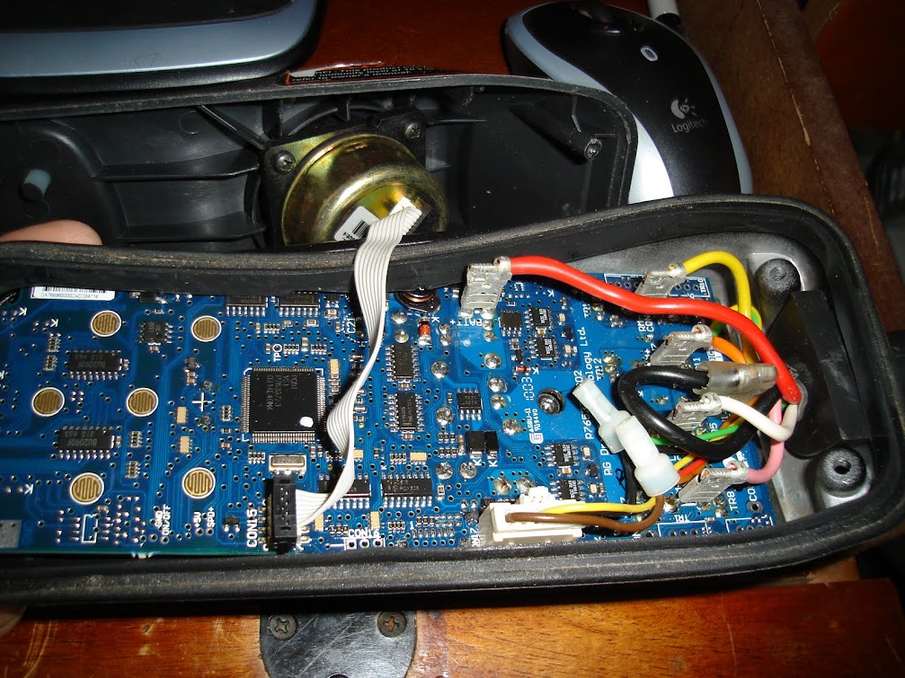
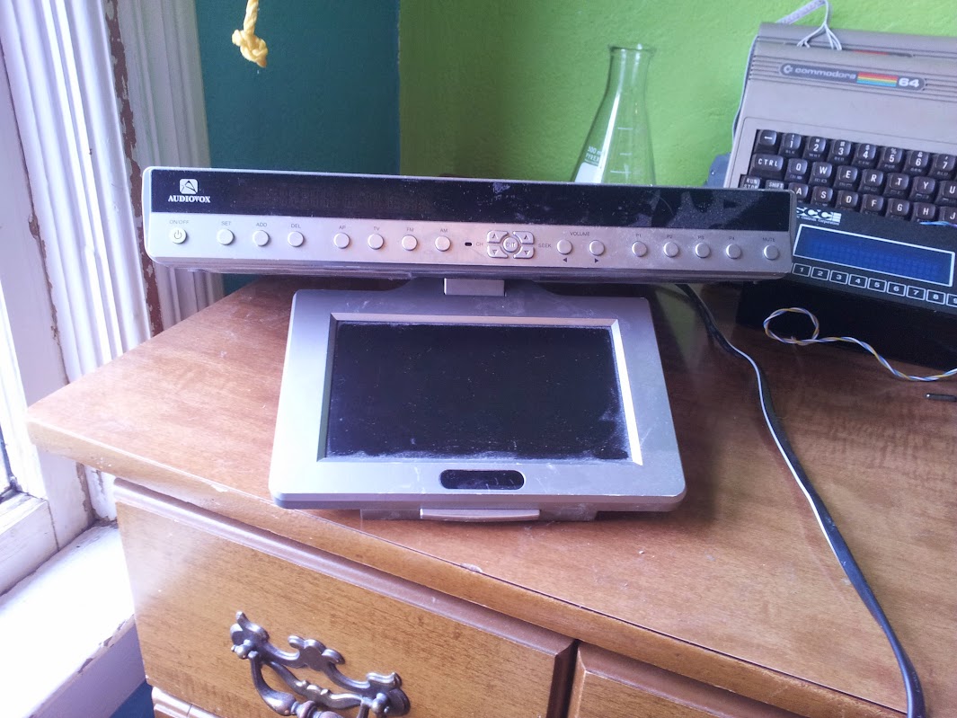
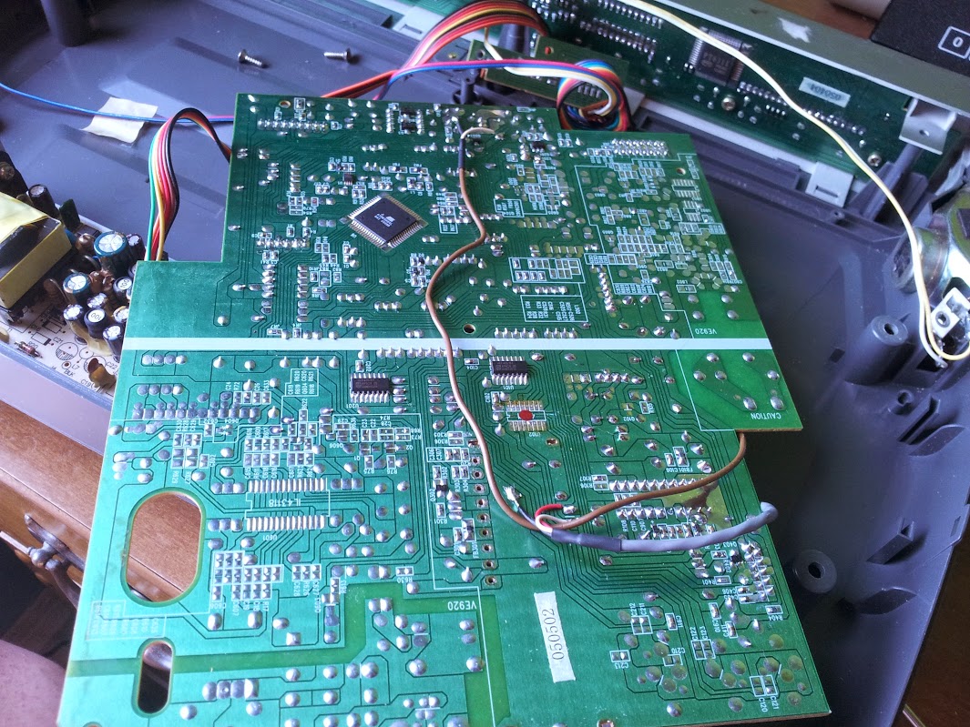
Archive for the ‘hack/mod’ Category

Sun Ray 270 to pi/monitor conversion

May 27, 2017

original glory

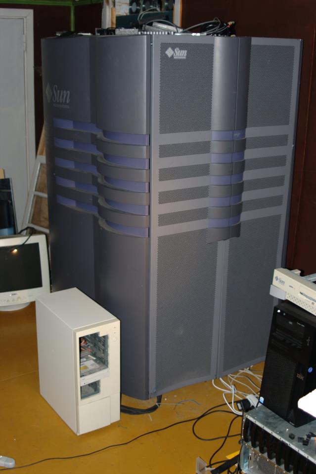
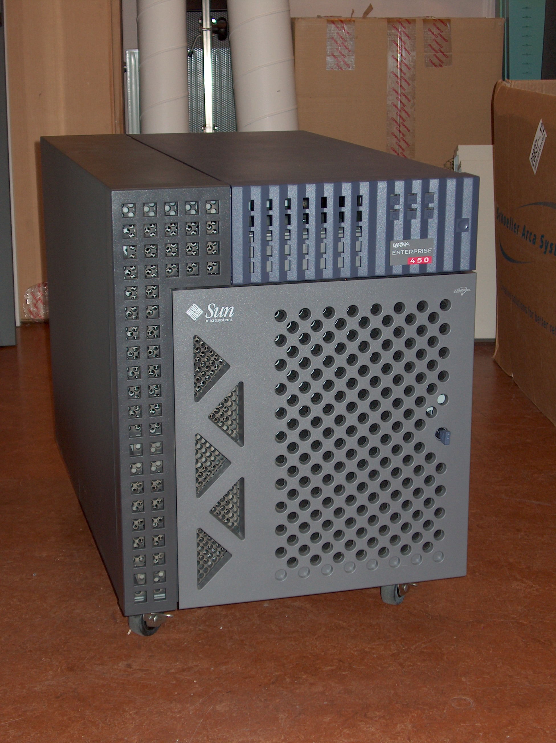
Sun Microsystems used to be one of the makers of very pretty hardware (if you like the color purple), but that era is no more.  Sun rays in particular are cool though.  The ability to move your desktop with your smart card to any terminal you want is awesome and really, the hardware is really well built.  Also, Oracle sucks.  Combine these two and you have no new hardware or support for a modern ecosystem of sun terminals.  I have tried and failed multiple times to get sun ray servers working and I give up.  I decided to make a decent tiny little thinclient/monitor out of my only LCD sun ray.
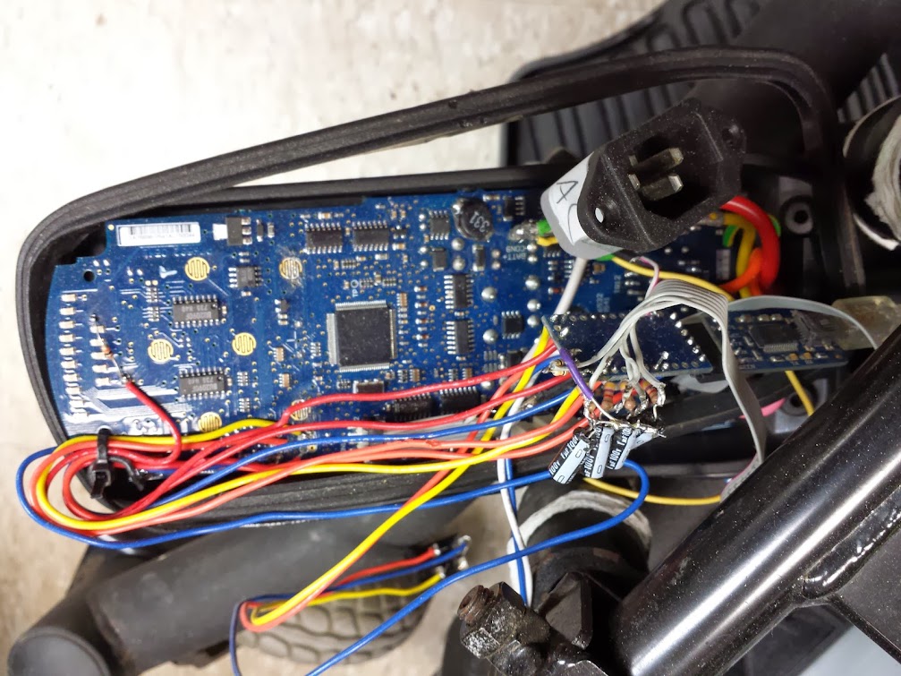
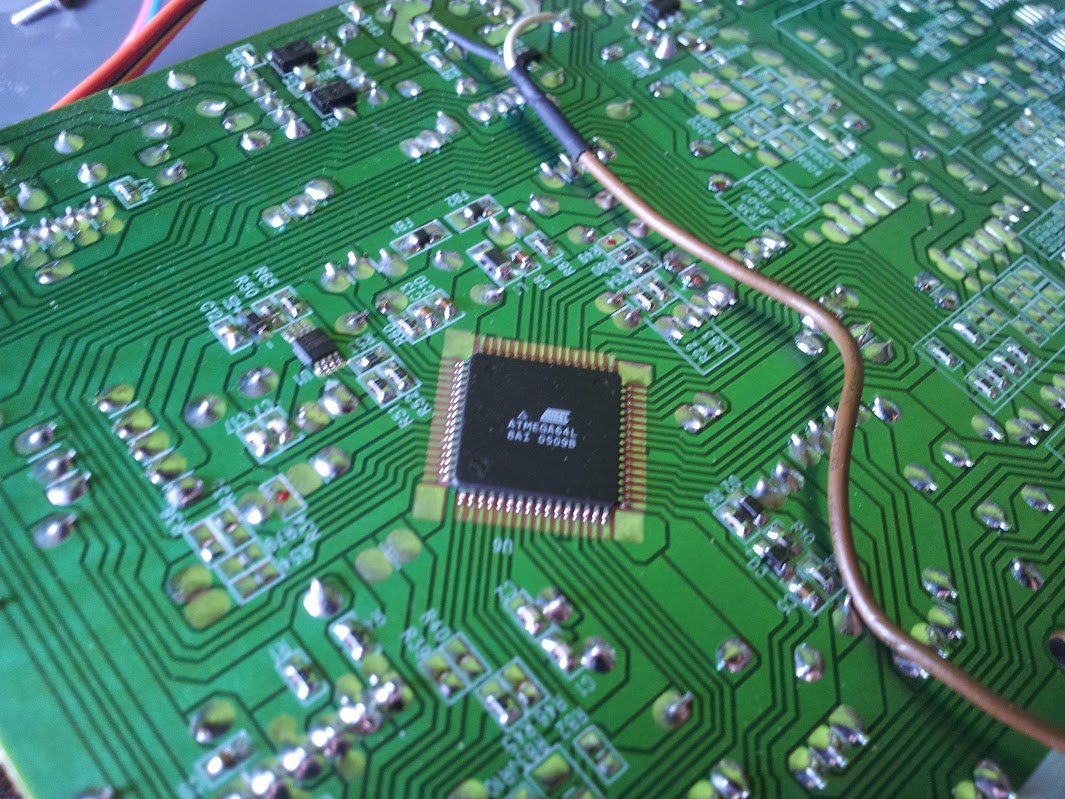
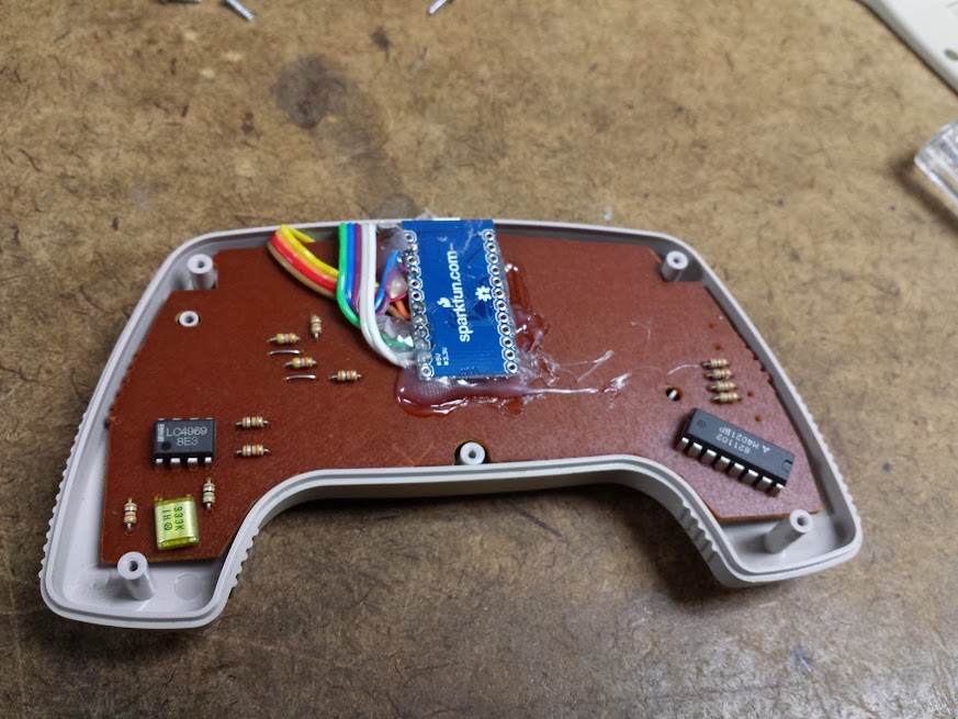
custom wiring

The first thought was to just have a pi contained inside it, but it became obvious that I was going to break out other ports from the generic LCD controller.  Doing that and not having HDMI would be annoying, so I added an HDMI switch to the deal.  This did not add much complexity, but it gave me more buttons to put on the front panel.  I decided to use the audio jack holes for the power button to the LCD controller and the input switch button for the hdmi switch, leaving one free to house an RGB LED that could represent which of the three inputs was active.  The power LED for the LCD controller went where the original one did, and the IR receiver went in the corner of the smart card hole.

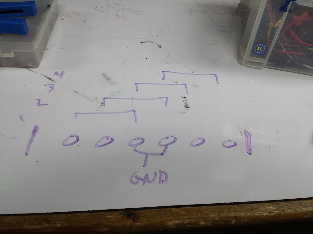
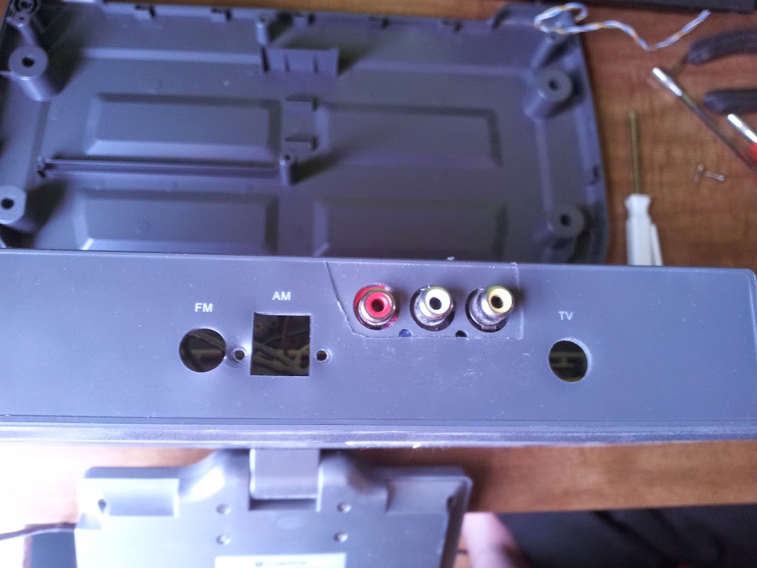
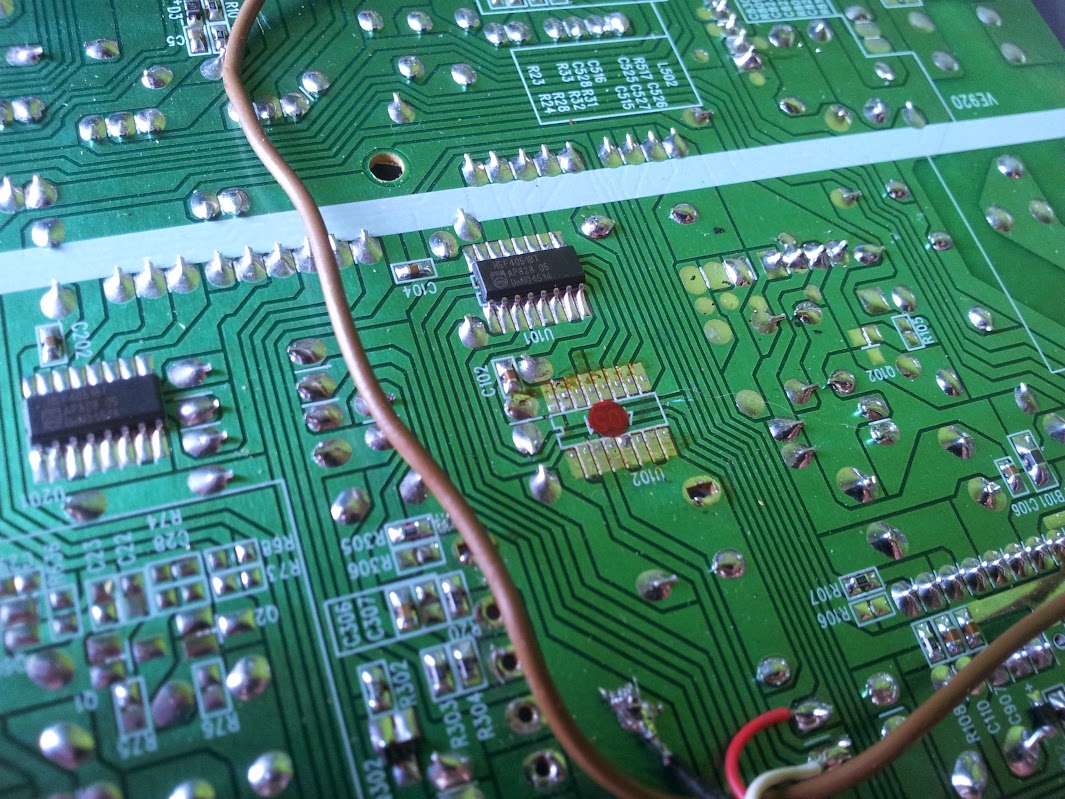
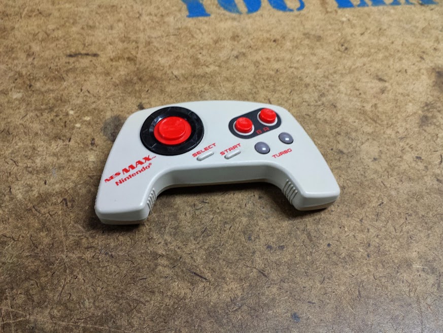
NEVER trust the silkscreen of the button functions on cheap controllers

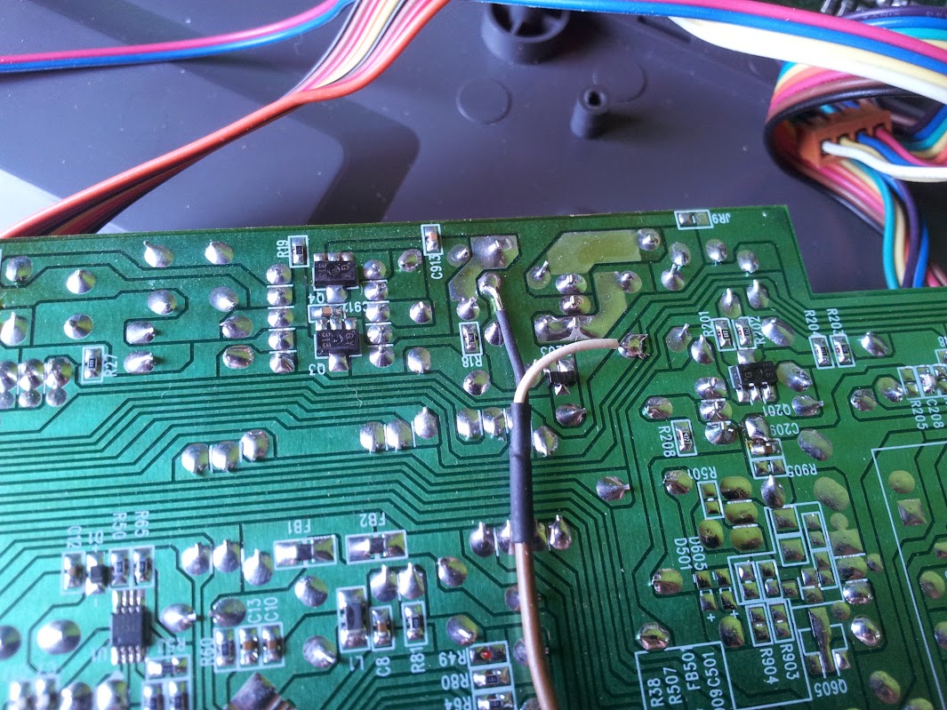
It turns out the bulkhead mount HDMI cables I bought have almost the same spacing for screw holes as the VGA ports the sun ray originally had.  I cut and mangled most of the case to fit the new contents and decided to mount as much of it to the LCD as possible so the clamshell could be opened for service.  I also added the 2 composite ports out the original serial port holes as they fit snugly there.
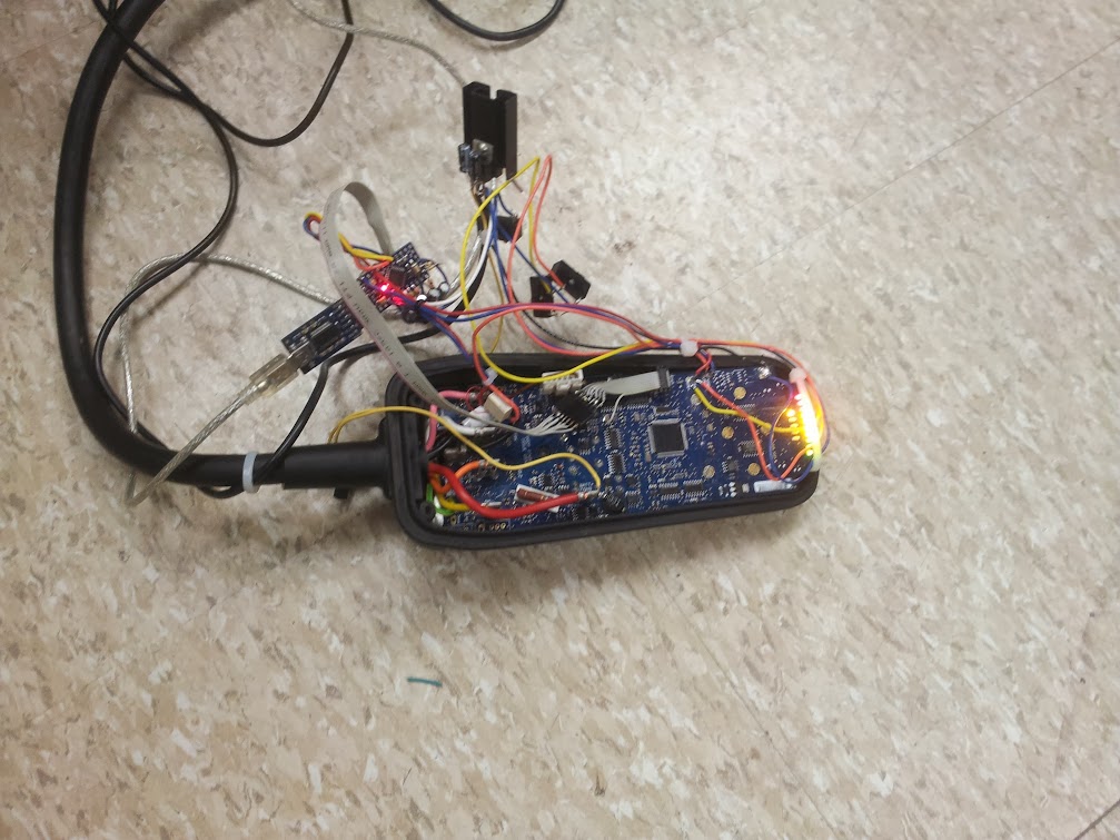
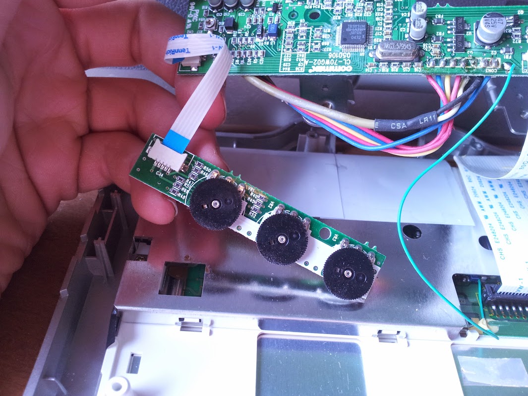
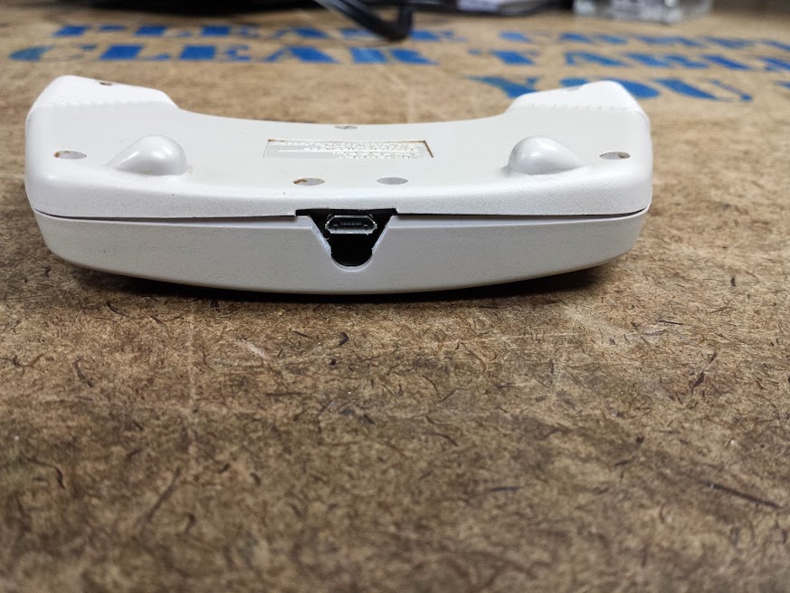
first constraint

The backlight driver went in first, it couldn’t move very far but I put it as far out as I could to leave room for the rest.  Then went the insulating layer (cardboard) and the LCD controller.  With that in and the video cable routed the PI and power supply for it went in easily.  The only hard one was the HDMI switch as it had ports out all four sides and there wasn’t enough space to glue it down anywhere.  After some fiddling it all fit, but I had to add a power switch for the PI because it didn’t like to come up if powered on with the monitor.  This power switch went in the SIM card port that this had for some unknown reason.

all laid out and shimmed with corrugated dead tree

This HDMI switch is actually really cool.  You can only switch between inputs that have signal, and it auto-switches when one comes online.  I’d recommend it for being cheap and useful.

sandwiched between insulating cardboard

This is now 100% more useful to me, it’s a wireless linux box that’s got a built in monitor for working on my single board computers.  I can download and write images right from the second input of the monitor.  If I had decided to spend more time at it I would have lined up the original ports with the USB, ethernet, and other jacks so it looked more stock.  I could have tried harder to get internal sound working on it.  I could have broken out the pi’s gpio to the slot where the smart card went.  This was already a dubiously useful mod for me, and while all those things would have been cool, I really wouldn’t have found them much more useful.

hacked

All of the pictures of this build are here.

TI-58 Calculator battery upgrade

May 15, 2017

After a weekend at Minicon I came back with plenty of goodies thanks to the trusting nature of Amtrak (look for a CDV-715 post coming up) and one of the smallest was this TI Programmable 58 calculator.

original

I love old bubble display calculators, thermostats, stopwatches, whatever I can get my hands on.

crusty

This repair seemed pretty simple, replace the old Ni-Cd batteries with new ones.  The challenging part was someone already did this once before.

you’ve had some cowboys in here…

The batteries were a snug fit, the power tabs snapped, and I ran out of patience.  The original TI charger for this was rated to put out ~3v although after the bridge rectifier easily identified was somewhere around 6V DC-ish.

looks like a rectifier, that can go

I decided that that’s close enough to 5 for 1977 and injected my new power source there.  My selection was based on what I had lying around which turned out to be a micro-usb lithium charger/boost converter that put out 5 volts and a lithium battery out of an old ipod external battery pack from radioshack long ago (I bought it before the advent of common charger/boost converters for single lithium cells).

all kapton’d up

Put together and with some kapton to hold it in place and a dremel to hollow out the case I successfully added usb rechargability to this old calculator.  I will admit that it is now incompatible with some of the add-ons, but I’m not terribly concerned as I intend to use it just as a pocket calculator.  All pictures (including others not in this post) are here.

useful once again

serialderp – completely non-autonomous arduino robot

August 11, 2016

This is an extension of the pervious robot, derpderp.  A friend wanted something to use for makerfaire Detroit to show off a bluetooth attached armband.  That sensor interfaces with python on a raspberry pi 3, and since I have some experience making python controlled robot platforms I volunteered to help.

The code I wrote just conflates the original derpderp code (which I use to drive the robot) with the wheelchair robot code that I use as a framework.  The additional things are setting the servo angle (what used to be the lidar platform), turning the light on and off (added to the lidar platform), and getting the temperature and humidity from an onboard sensor.  When making this change I found that the battery wasn’t working so I dug up the charger.  Then I found it wasn’t charging… so I tore apart the charger and bypassed the fuse.  It still wasn’t charging so I tore apart the battery and bypassed the fuse.  Then it finally worked, but that battery was so anemic anyway I decided to upgrade it.

The original battery was a 9.6v 500mAh battery, I replaced it with a lithium jump pack.  I had bought this jump pack for my car with an unreliable battery (which I eventually replaced) and somehow ended up running it over in my driveway.  I don’t even remember taking it out of my car and the next day it’s in pieces on the driveway.  After looking it over it still looks intact.  The plastic is shattered and the box that goes between the battery and the jumper cable clips has been crushed and the open frame relays inside will never function again.  That box, as far as I can tell, has a microcontroller in it that just supervises the closing of a bunch of little parallel relays to connect the care battery in parallel with the lithium pack (no protection whatsoever).  To me that means that I now have a connector and cable that will give me an unregulated voltage that I am glad to use for my motor power.  The charger board for the jump pack has a variable dc-dc on it to make different voltages, a usb port, and a flashlight.  I took the flashlight off and drove it at about 20mA with a resistor and a FET off the regulated 5V I’m making on the robot.  That’s the headlamp on the robot and it’s steerable with the servo as well as PWMable.  The control board is now only useful as a charger for the bare lithium pack as the battery voltage is not passed through it before hitting my robot.

The commands are:

sCmd.addCommand(“HUM”, humCMD); //no args

sCmd.addCommand(“LIGHT”, lightCMD); //0 – 255

sCmd.addCommand(“TEMP”, tempCMD); // if ‘1’ then F, if ‘0’ then C

sCmd.addCommand(“TURN”, turnCMD); // sets turn -1000 to 1000

sCmd.addCommand(“SPEED”, speedCMD); // sets speed -1000 to 1000

sCmd.addCommand(“ANGLE”, angleCMD); // sets angle of servo, 20 to 160

That’s a fairly easily controlled robot.  I don’t know exactly how the project went because I was on vacation for the week leading up to makerfaire, but there were some problems sending the commands from a raspberry pi (and I still don’t know why, it was over USB).

code is here.

pics are here.

autonomous version is here.

derpderp – Autonomous arduino-based robot

July 15, 2016

Here is yet another autonomous little robot that rolls around avoiding walls, this one was also made for a hackathon much like the venerable wheelchair robot.  The difference here is that insistence that code be developed on an SBC slowed development to the point that many features had to be dropped.  The point of this robot is to venture into unknown territory and send back sensor readings (distance, temperature, humidity, light level, barometric pressure) so you don’t have to go in blind.  The need for autonomy come from us not having a camera with which we could drive the robot.  The goals as best as I can remember:

  • autonomous exploring (drive forward, avoid walls)
  • wireless telemetry
  • large array of sensors
  • manual over-ride
  • make duck noises

The only things that got implemented out of these were the first two.  I put a lot of effort into making the only touchscreen we had (a SainSmart 2.8 inch TFT LCD) work as a UI for telemetry and control but was no able to make it work.  I still cannot even after buying the adapter for the arduino mega.  Usually I’m able to get around shitty documentation by digging through the code of the libraries, but this one beat me.

The large number of sensors… We had a BH1750 Digital Light Sensor, never got it to work.  We had a BMP180 Barometric Pressure/Temperature/Altitude Sensor, didn’t have time to make it work.  An HC-SR04 ultrasonic sensor, also never made it do anything.  A DHT22, the simplest sensor we could have installed… nope.  So, we had absolutely no sensor readings but it had a bunch of stuff plugged in so it looked impressive.

The actual navigation was done using a LIDAR Lite, which is a really cool i2c lidar sensor.  This was borrowed from a FIRST team and unfortunately no longer resides with the robot.  I thought about getting another one, but it’s just too expensive to put on a robot that I actually have no use for.  The chassis was the absolute biggest, most expensive RC car that walmart had to offer.. a New Bright 1:10 Radio Control Ford Raptor Truck, Black/Green.  No, I wasn’t much impressed either.  For a chassis this had loose ball joints, an anemic little lithium battery pack, and a motor that was rather poorly geared for torque.  But if the chassis was perfect then we’d have no fun accounting for it later.  The motor control comes from a Sparkfun Ludus Protoshield (which I got in a ding/dent deal and is not labeled like that on mine).  The control is just two-bit direction and a pwm line for speed.

Sparkfun ProtoCAT board

Being in the IEEE lab at MTU we had the advantage of a 3d printer.  They may have taken away the band saw and drill press because someone took off the safety switches and didn’t either restore them or hide them well enough, but we could still make small plastic parts over the course of several hours.  We made a bracket to hold the LIDAR to the servo and cut up a chunk of an old computer case to affix the servo to the chassis.  Now we had a chassis with enough sensor to let it move.  You may notice this is the exact same setup as the wheelchair robot with the exception that it’s smaller and much lower power.  When you have a hammer and all that…  It should not surprise you that the same person wrote the code for that as this one.

The wireless part was going to be a whole custom interface between two esp8266s to allow for touch-screen control and telemetry… Well, when it came right down to it I flashed the wonderful ESP-Bridge firmware to an esp8266 and clamped that onto the serial port of the arduino uno.  That worked for a very short while and then stopped.  I then replaced the esp8266, put a voltage divider on the rx pin, flashed it again and then it kept working… oops.  This theoretically gave manual control and some sensor data, but in fact it just gave updates from within the code.  That meant a constant stream of almost nonsense that looked pretty impressive to the lay-person.

The duck sounds were actually going to be quacks made by a speak-n-spell I found at goodwill, but hacking that never actually happened.  That may be an upcoming post, because using one of those for a speech synth has always been a plan of mine.

The battery was the same one that came with the RC car, a 500mah 9.6v lithium pack with charger.  Really anemic for this use but it worked for the little while we needed it to.  I upgraded that with a later revision.  The bus power is provided by a little 3A adjustable dc-dc regulator from ebay that got set to 5V and had the POT glued down.  This is much better than the linear regulator that would just dump 50% of the power from our tiny battery as heat.

The code is here

The pictures are here

the hackathon post is here

Wheelchair robot

June 29, 2016

Back in college (yeah, those were the days) I was in a hackathon with a couple other guys.  What we decided to do was to build a robot platform out of a wheelchair.  While researching for this article I found out that we are not the only ones to do that with this style wheelchair, but I think we implement the most functionality.

We chose to interface with the existing controller since it already does what we want.  Power was not an issue as you can see the battery voltage is brought right to the controller and helpfully labeled.  The inputs and outputs were:

  • in: power state (using an analog pin and LED)
  • in: power switch (manual control passed through our code)
  • in: speed up switch (manual control passed through our code)
  • in: speed down switch (manual control passed through our code)
  • out: power relay (controls the power switch on the pcb)
  • out: speed up (controls the speed up switch on the pcb)
  • out: speed down (controls the speed down switch on the pcb)
  • out: speed/speed2 (sets the position of the virtual analog stick)
  • out: turn/turn2 (sets the position of the virtual analog stick)

In addition to these we also used the usb-serial converter on the serial lines to communicate with the laptop.  Through incredible self restraint we didn’t implement the horn functionality.

Here is our modified controller.  You can see the joystick connection is modular so we could probe the lines in circuit before connecting our controller to them.  That proved absolutely essential because this controller is a little smarter than you might imagine.  The joystick has 2 separate potentiometers for each axis which we drive with identically controlled pins on the arduino pro mini.  The controller also throws an error when the virtual joystick goes too far out of the range of the mechanical joystick.  we have capped these pwm outputs using a helpful map function:

speedOut = map(speedVar, 0, 1023, 50, 210);
analogWrite(SPEED_OUT, speedOut);
analogWrite(SPEED_OUT2, speedOut);
turnOut = map(turnVar, 0, 1023, 50, 210);
analogWrite(TURN_OUT, turnOut);
analogWrite(TURN_OUT2, turnOut);

This allows us to work in 1024 increments of turn and speed while knowing we won’t trip the internal protections against an unplugged or shorted joystick.

The code written here is non-blocking and runs in a continuous loop.  It checks to see if any switch is pressed and does the corresponding command if needed.  It then checks to see if there are any serial commands that need executing (I’ve used this serialcommand library before).  Once it executes any needed commands it sets the virtual joystick based on the internal variables stored for the position.  It checks to see if it has been more than 3000 loops since the last command given, and if so it re-centers the joystick (a crashed python program sent it driving off since we no longer had a spring return joystick).  The commands it takes are :

  • TURN [0-1023]
  • SPEED [0-1023]
  • SPEEDLEVEL [-1,1]
  • POWER [0,1]

Turn and speed set the joystick position (512 is center), speed level pushes the relevant up or down speed button (which just scales the joystick, increasing or decreasing the max speed), and power turns on or off the wheelchair controller (not our controller).  Since these commands just push buttons it is not possible to know if you are at the max or minimum speed (we did not read any more LEDs, but you could).  We did, however, implement the power LED.  When you want to turn on the controller it checks to see if it is already on and then sets the joystick to center, presses and holds the button for 100ms, then releases the button.  This is also part of a safety interlock to keep the wheelchair form just taking off when turned on.

The power connector passes 12V for charging and is labeled as such. I didn’t do that part, I promise.

The power connector passes 12V for charging and is labeled as such.  I didn’t do that part, I promise.

The next bit of software I didn’t write.  We interfaced this robot with a laptop and a kinect for doing depth mapping.  You can see that code here and your interpretation is about as good as mine, but I will try.  I will say that this code is sending speed, turn, and power commands as one even though I am processing them individually.  The speed up and speed down are not used (we used the manual switches in the robot).  The logic in the python code looks at a center depth, a left and right side.  If the robot is clear to move forward it does, else it goes left, else it goes right, else it backs up.  The behavior is very simple and the movements around our oval-shaped hallway were interesting.  There’s enough lash and randomness in the mechanics of the wheelchair to make sure it never gets stuck even without more complex self-correcting code.

That’s it.  How to make a wheelchair based robotics platform and how to interface that low-level arduino control to a python script.

pictures are here.

code is here (forked in case he wants to bring it down)

2.4Ghz analog camera scanner

June 29, 2016

This story has a part ‘back in the day’ and a part just a couple months ago.  Let’s start with the most recent part.  I decided that I want cameras around my house.  I didn’t say in my house, I said around my house.  I would like to be able to see my front yard, back yard, driveway, and maybe even down the street a bit.  I want cameras inside, but this is absolutely not the way to do it.  I came by a number of analog cameras with 2.4ghz transmitters, but the receiver I had used analog tuning.  I never worked out whether it would pick up all 4 channels of camera (there are 4 in the standard I’m familiar with) or just fine tune on 1 but either way I decided that using analog tuning is harder than it needed to be.  I went on ebay and picked up a 4 channel receiver with a switch going between channels.  With that I got all 4 of my cameras on different channels and able to be picked up by the receiver.  In the process I found a camera outside that picked up my hackerspace (probably by the landlord based on where it was and was pointed).  Now, even if I didn’t already not want these cameras inside… I would like to think this would have done it.

Before I go on with this hack (which is, as always, half finished) let me bring you back to my inspiration for this one.  If you look up the origination of the term ‘wardriving‘ which is what I grew up doing (driving around picking up people’s wireless networks and using/breaking into them) you will find ‘wardialing‘ which is basically robo-calling for modems.  This was popularized (if not originated) by the movie WarGames because before Matthew Broderick was doing his best Gene Wilder impression, he was impressing girls with his computer skills.  This is a different kind of automated scanning attack, the one I’m thinking of is ‘warspying‘.  Eleven (!) years ago Systm launched and had an episode with a howto for building a handheld unit for detecting and displaying unencrypted wireless cameras.  I wanted to use that technique to drive this switch from a raspberry pi (or any other computer with gpio).  Where they used a small pile of discrete I/O to accomplish a dedicated scanner I used a simple demultiplexer, a 74155, to control 1 of 4 lines with 2 GPIO.  Since I only need one line grounded at a time I can use this technique to save pins.

You can see from this switch diagram (or the description in the Systm video) that the switch has 6 pins and 4 positions.  If you ground the two center pins then you ensure that one of the outer 4 pins is grounded in each switch position.  Rather clever for what would otherwise have been a more complicated mechanism. That being said, this doesn’t scale very well.

I really wanted to replace the whole board here, or at least make the unpopulated stuff work but that just never happened for me.  For anyone else with one of these modules, now you know what’s inside so you’re prepared before you go tearing it apart.

Now you can see how I made a camera receiver interface with a raspberry pi.  If you send 00 out two pins you get channel 0 of video, if you send 01 you get channel 1, same for 10 and 11.  Until this actually gets used with GPIO I have set up a 2×3 jumper block with power down one side, ground down the other, and the two data lines in the middle so they can be pulled high or low.  There is no ‘off’ since that wouldn’t matter, the video capture card is connected straight to this module and there is no need to switch it out for anything else.  If you needed to it could be done with a 4051 analog mux though.

pictures related to this project are here.

Drill chuck replacement

June 28, 2016

For any of you plagued by modern power tools, I have a reminder for you.  Even if you have to get a drill to finish a project right now and your only option is a speed chuck there is still hope.  Just because you had to buy a new tool doesn’t mean you need to be stuck with crap forever, upgrade it! By using a hammer, a large allen key, and some stiff impacts (don’t burn up the motor trying to do this with the drill) you can remove that new crappy chuck and put on a nice old Jacobs chuck with a key.  Gone are the days of skinning your palms when you try to get a drill bit in and out.  Or the instances when you just can’t get enough torque to keep that hole saw from spinning.  With your newly installed chuck and key you have the needed mechanical advantage that makes a drill worth using.  Ever wonder why not even the cheap companies use a keyed chuck on their larger models? That’s right, you can’t get the needed torque.

Hacked LCD (given composite input)

June 22, 2016

There was a time that I would take any display that I could get my hands on and try to find a composite video signal inside it.  With that information I could modify it to take composite input from my source and I’d have a portable little lcd that I could use with my commodore 64, or raspberry pi, or… game console… this was before the C.H.I.P. or other single board computers with composite became popular.  That technique is still useful today because of the continued prevalence of composite video and the ubiquity of displays that can eat it somewhere inside.

The patient is this audiovox under-cabinet television and radio.  Let’s have a look inside.

My that’s a lot of empty space! if you look closely you can see where a dvd module would go, if this unit had one (!).  I have already hacked this one so there are some things missing.  First, you can see a lack of any RF cans full of tuning equipment, so this can’t pick up video or audio over the air anymore.  I’ll show you a picture of the back soon, but for now look at how sparse the board is (there’s more underneath but look at the unpopulated bits up here first).  There’s a section off to the right that looks to me like a modem.  I don’t know what that was for, really.  If anyone has an idea please let me know because I’m interested.  There’s also a set of unpopulated parts (including what looks like a mains section ) on the left side of the board.  That could be if there wasn’t an off-board power supply, I’m not really sure.  Looking at the parts that are present you can see a long DIP chip with some hefty capacitors, that’s the audio amp.  The connectors just above it in the picture go to the speakers.  The pole of odd stuff at the top of the board is the power supply for the VFD, there’s nothing else that would need those parts on this board.  Let’s rotate.

There’s my hack and you can see where the radio and TV tuner went.  You can also see I didn’t drill those holes, there was an option on this model to come with composite input.  I didn’t try to reverse engineer the extra feature, I just removed the other stuff and used those inputs.  Rotate again.

You can see there’s a bunch more stuff unpopulated, and the section I thought was an unused mains power supply says caution.  Enhance.

Wrong section but I can talk about it anyway.  I find this a little strange, I don’t usually see atmel ICs in the grade of consumer electronics I dissect.  I will point out I could reprogram this to add features and basically do whatever I want.  I would rather… no, this is public and if I use some colorful example someone will use it as evidence to convict me of something.  Let’s just say I won’t be doing that today.  Reposition.

Ok, here’s where I patch in the audio.  I tapped off two pins that I found near the amplifier and I removed the 4051 feeding it so that only our audio is heard.  Reposition again.

Here’s a tricky one, I actually fired up a video game, took a probe, and started injecting composite anywhere on the board I thought likely to work.  I could have probably guessed as well, but this worked really well, especially with no tuner trying to drive the screen black.

This is inside the LCD itself, there was a board to control brightness, contrast, and stuff.  You can see the ribbon that goes between the LCD and the body, I didn’t want to touch that.  So there you have it, that’s how I repurposed a thrift store screen into a portable LCD for use with my raspberry pi.  If I desired there’s plenty of room inside for the pi and a bunch more hardware, the power supply would work well too.  This currently tests composite cameras for my insecure 2.4ghz camera setup that I’m planning around (not inside) my house (post coming soon).

All photos here.

UPDATE 12/19/2022

I finally decided that this is too big and annoying of a form factor to use much. As such I reverse engineered the cable between the screen module and the bigger under-cabinet unit.

I couldn’t find an off-the shelf controller to drive this screen, which is fine because it wouldn’t fit as nicely in this shell. The connector across the top is as follows:

12v, gnd, composite video, unknown, 3v?, IR data, 5v for IR

Interesting thing about this is the only ground wire on that connector is the shield of the cable that carries the video. I wouldn’t have designed it that way… That being said, after hooking up 12v, ground, and composite in I have a working monitor.

I did lose audio, but I think I have a solution for that. The female barrel jack cable I used is actually a barrel jack splitter that I cut one male end off. I fed the unused end back out as a 12v pass-through cable. With this I can design a simple stereo audio amp and power it from that barrel jack. I certainly have some esoteric audio amp chips that warrant a run of 5 specialized boards to use them.

Now, no one point out that the sharp tr3y31m can have rgb in, I’m pretty done with rgb right now.

ultrasonic adapter for quadcopter

June 20, 2016

This has been in my queue for quite a while (and I’m pushing it out now with no pictures, oh darn).  When I was in college we were working on a quadcopter.  I think our descendants are still working on the same one.  When I was there we had an ardupilot board and were making a frame, tuning the hardware.  One of the optional extras that the ardupilot code can take is an ultrasonic sensor.  The sensor they use outputs an analog voltage.  The sensors I had around used a trigger and echo pin.  Rather than modify the ardupilot code I chose to throw a pro mini at and adapt my sensor to what the ardupilot expects.  Here is my code for how to make a DYP-ME007 act like a Maxbotix ultrasonic sensor.  For anyone who wants to get away with a cheaper ultrasonic sensor here is my code, if it looks simple that’s because it is.

NES Max Mouse

June 19, 2016

This is actually a nice polished mod for once.  I did this a while ago, so I don’t have all the hoops I jumped through fresh in my head (and as such this will be short).  I picked up an NES Max at a garage sale for a dollar or two, it’s this really cool controller that makes the D-pad feel kinda like an analog stick, but it’s still digital.  It’s also got 2 built in turbo buttons.  That’s right, turbo buttons from an OEM.  I’ve seen people removing the brain of NES controllers and using then as joysticks or keyboards for games, but I had a different idea in mind.  How about a mouse.

This thought came from the fact that the Max UN-D-pad looks a lot like the psp analog stick.  It slides, rather than tilts.  It’s also only slightly larger.  With that as true analog control and 4 buttons I had all the makings of a mouse.  This controller with it’s turbo buttons seemed like the perfect reason not to remove the controller IC and instead to interface with the NES pad just like an NES would.  My work was basically done for me in the form of the the NESpad library.  Now, I realize the NES controllers are just shift registers, but sometimes it’s comforting to know that someone else had enough success with their specific implementation to publish their code.

My analog reading code is very… primitive.  I could certainly use some fine tuning in the acceleration, diagonal boundaries, and any other advanced algorithms, but this works as a proof of concept.  I tried to modify the controller as little as possible, I think I made it look quite good from the outside.  Now I have a usb mouse, with turbo click! I’m sure someone who felt like it could do this with an adafruit feather and make it bluetooth, but I use what I know, the atmega32u4.

The code can be found here.

The rest of the pictures can be found here.