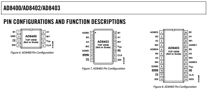
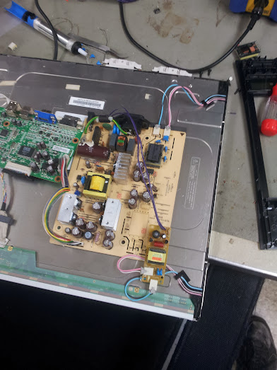
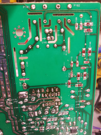
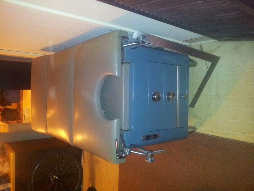
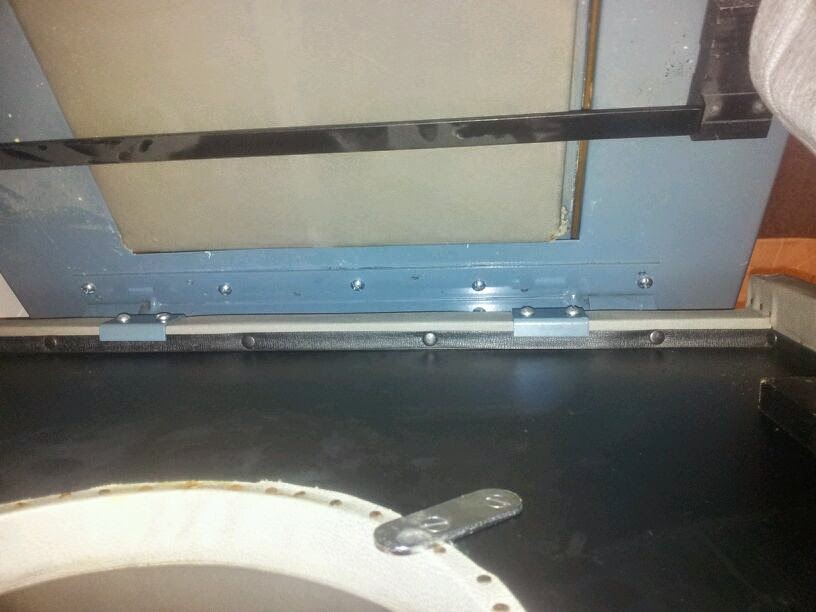
So, a buddy of mine just picked up an Amray SEM. I have no idea what model, but apparently there’s a mailing list community of hobbyist and they’ve never heard of this particular model. That’s a good sign. After trying to set it up several problems were found and fixed (I’ve got to start documenting things again) we came across this poser. There are four thermocouple inputs on the board, amplified with some opamps, and that signal is piped to a single display (galvanometer) via some analog switches. None of that interfaces with the microprocessor, except for the fact that all four analog signals (post amplification) run into four of these CA3098E hardware hysteresis chips. Simulating a signal for the thermocouple using a 10 turn potentiometer and a AA battery we found that the hysteresis chips were not doing what they should. The datasheet is pretty clear that there’s a high and low setpoint, and input and an output, and the output was not changing when the input went above or below the setpoints. We really didn’t have a way to tell what else it should be doing so we declared them bad.
With no source for these chips other than some from e-bay which were probably salvage anyway we resolved to build a replacement. The first thing that came to mind is using a literal textbook as reference to build the textbook op-amp hysteresis circuit. There was a problem with this approach: despite thinking we came up with the right equations it did not simulate right in LTspice. In the end it ended up that comparators are different than opamps in ways this circuit cares about, but it only took like three hours to figure that out. The problem I had with that circuit was that it only used one setpoint and some carefully calculated resistor values, I’d rather it be a real drop-in replacement for the original chip and take the two setpoints that the board has trimpots for so it could take the original chips if we come across ones we want to use.

Matt’s circuit, smaller but requires a different setpoint and if you want to change it you have to recalculate those resistors
My circuit is an example of brute force in electrical engineering. No calculations, no carefully picked resistor values, just building blocks. Problem statement: we take one input and two setpoints, switch the output high when the input goes over the first setpoint and the output only goes low when it goes below the second setpoint. The output of the entire circuit is open collector and can be pulled up to whatever the output wants, which is useful for someone working with chips that are basically only good to 5v. To me this sounds a lot like an SR latch, you set the output high with one pin and reset it (set it low) with the other. You can build this latch out of NOR gates, I used NAND because we have buckets of 7400 chips I wanted to use up. To drive the 7400 chip I needed a 5v rail derived from the 15v that drives the chip. Rather than using a linear regulator which would burn a lot of that as heat I opted for an off the shelf buck converter hardwired as a 5v output (the practical upside of which is that there is now a usb port inside the machine if you need it for anything). The comparators that drive the input of those are an LM339 (good to 15v) and I used three out of the four in the overall design. The output of the latch is used to drive that third comparator which is compared against a resistor divider making half of the 7400’s power rail so it simply follows the output. This buffer is to give the output of the circuit an open collector output as the 339 is just that (I’ll have to remember that trick when interfacing with different voltage systems).

My circuit, bulky but perfectly replicates the subset of this chip that we actually use
The final design goes like this:
Input goes to one input on comparator A and one input on comparator B
setpoint A goes to the other input on comparator A
setpoint B goes to the other input on comparator B
15v drives the comparator and the buck converter to generate the 5v rail
comparator A and B are the inputs to the 7400 SR latch (pulled up to 5v since they are open collector)
5v rail is used to drive the 7400 and generate the 2.5v reference voltage
one of the outputs of the SR latch goes to comparator C
the 2.5v reference voltage goes to the other input of comparator C
the output of comparator C is the output of the circuit (pull up to the right voltage is on the PCB we’re interfacing to
This circuit is a real challenge because you can flip the polarity at basically any point, and I have purposely left out any mention of which is correct because I don’t remember what I did but at one point it was wrong and at another point I fixed it somehow. You also have another two NAND gates to use which can be used as NOT gates if you don’t want to swap the inputs on a comparator you wired wrong. This is an interesting project for using analog and digital components as well as interfacing to an existing circuit without using any programmable parts.

Yeah, my fix is kinda like this