OK, so this is one of those days that starts with big plans and gets derailed seemingly because those plans were so well thought out. I come from a group of people that spend their days just repairing things because they’re there. We have taken it in stride to develop techniques for repairing commonly thrown out items and apply our experience to new items as we get a hold of them, but we rarely document our work or share our knowledge beyond the confines of our lab. This is the story of what happened when I tried to document what I figured would be a routine repair on a common model LCD monitor.

Our Patient
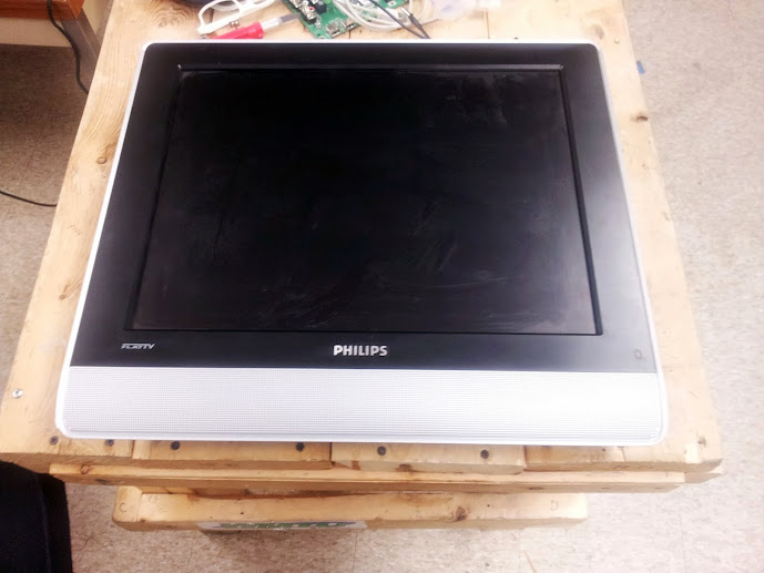
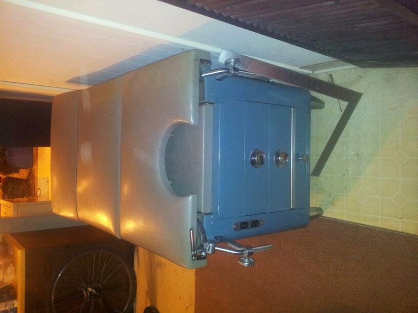
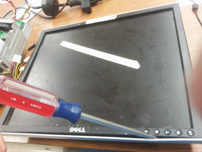
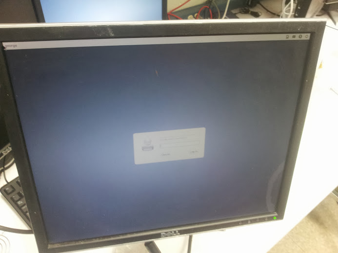
The monitor (as you can see) is a Dell 1907FPt 19″ widescreen LCD monitor. The first thing I recommend when you have a device of any kind to repair is to look up that model (or series) and see if anyone else has encountered problems with it. Hopefully you’ll run across a helpful blog post of someone who took the time to explain the steps they took to debug and fix theirs, so you can cut down on the time it takes to fix yours. I, of course, didn’t do that. I have no idea what the common failure modes of this monitor are and what the commonly accepted fixes are, so I blazed my own trail to some hilarious consequences. Seriously, do as I say, not as I do. For every blog entry of a moderately successful hack/repair I have there are a dozen failed ones that could usually be avoided by spending some more time researching and less time breaking things. In the future I hope to post my failures with notes for future pioneers, but my successes are usually still around after the fact so photos are easier to take (since I almost never take them during the event, but months after).
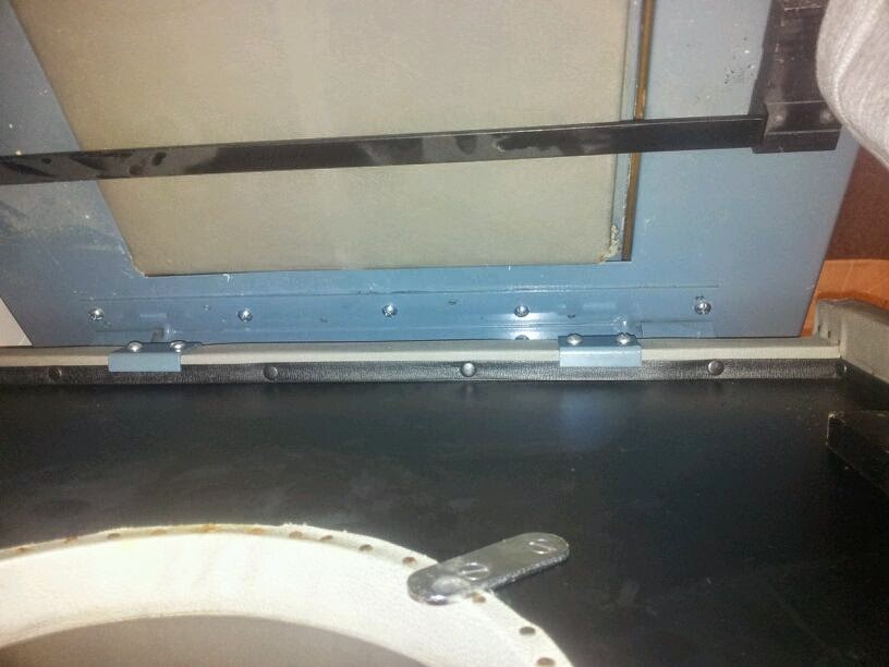
Now, having opened more than my fair share of Dell monitors I thought I’d itemize just what steps are involved. First you need to remove any visible screws, this usually just consists of the four phillips head bolts on the back (seen above). Next you need to insert a spudger (yes that’s a technical term, look it up) into the gap between the monitor back and the bezel. That separation into two pieces is the entirety of the plastic casing on this model.
step one
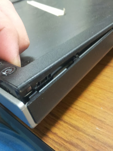
tabs exposed
keep going, almost there

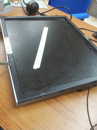
and there you go, dis-assembled
Once you get the back off of this monitor you will inevitably hear a clatter as something falls to the floor and hides among the junk there until you figure out what exactly was missing so you know what to look for. What you are looking for is a small plastic button and spring that retains the base to the monitor. The button is a Dell thing, they have brackets on their stands that allow you to use your monitor with only that stand and not that of another Dell monitor. These stands are “tool-less” which is slang for “our main consumer base can’t operate a screwdriver”. The monitor itself has VESA standard mounting holes, but the stands are mostly useful for the monitors with which they came (although I may explore the hacking I have done on these stands in a later post).
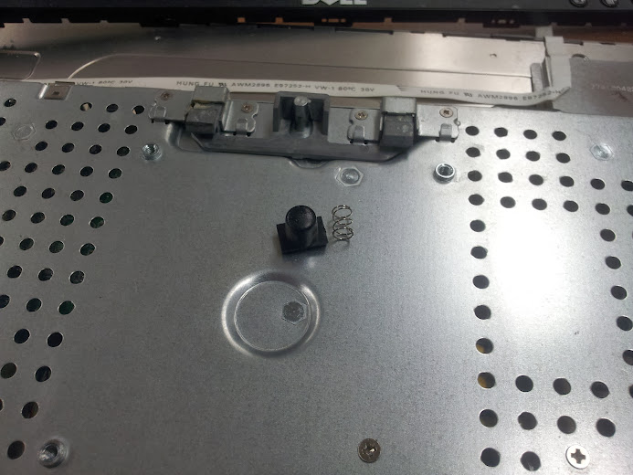
The button and spring, free without the back
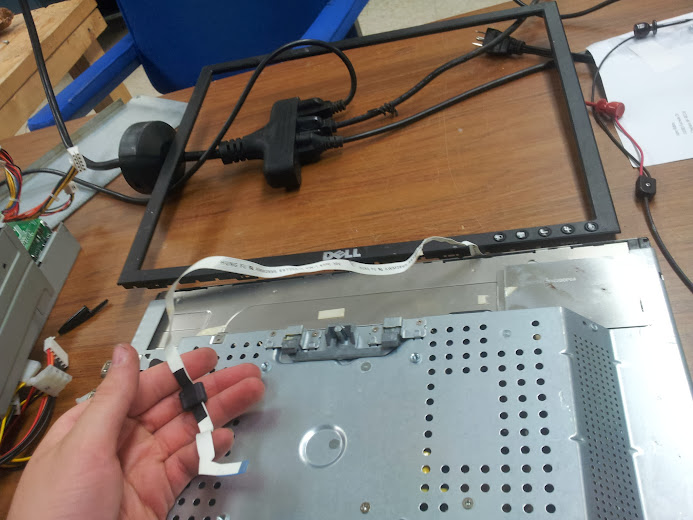
carefully remove this ribbon cable and the double-stick tape that holds it to the monitor casing
Now we need to just keep removing screws and remember where they came from. You can usually ditch the shielding if you don’t care about potentially harmful interference as covered in FCC part 15.

remove one cover over the inverter wires

and the other
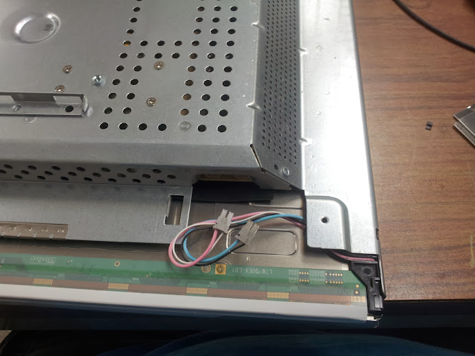
remove the inverter wires from one side

and the other, while you’re at it remove the screws that hold the monitor to the controller board housing on both sides

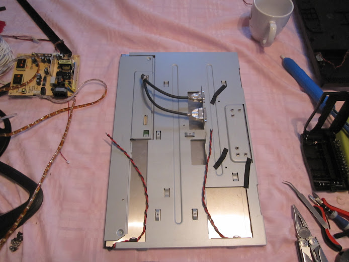
the panel without any controller, power supply, or inverter
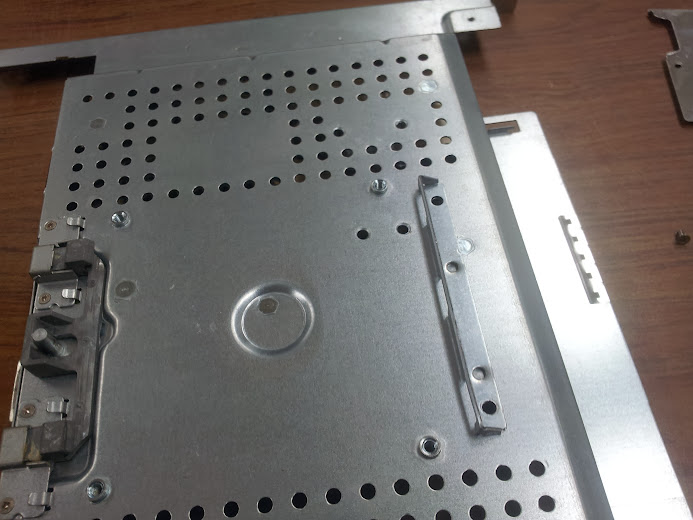
now remove the screws that hold the heatsink to the casing
screws seen here (note they are flat, they mount flush with the panel

power supply board has had it’s screws removed
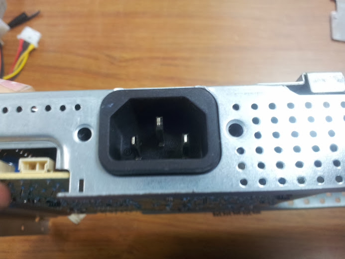
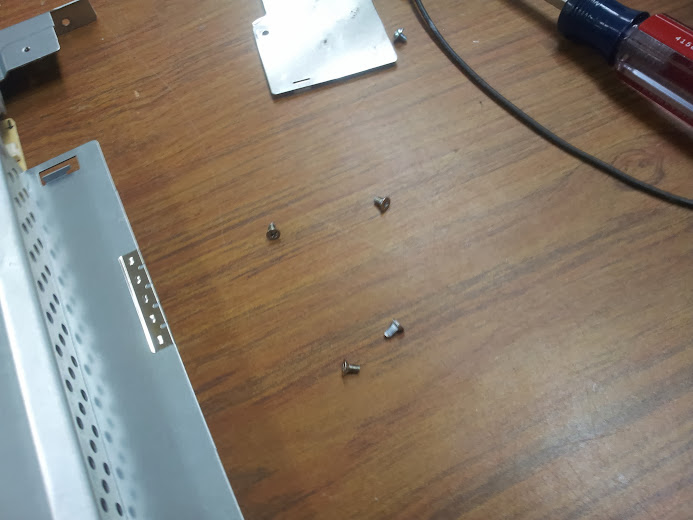
mains plug with screws removed

screws in question
Not pictured (I know, with all these pictures I forgot one) is the removal of the logic board’s retaining screws and the mounting hardware for the d-sub connectors (VGA and DVI, although DVI’s not a true d-sub).
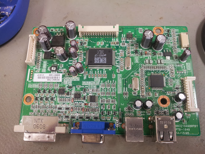
controller board
Here is the controller board. There were no bad caps on it, which is a shame since that would have been an easy fix (unless the problem caused a chip failure). On the bottom are the ports exposed to the outside. DVI, VGA, USB-b, and a dual stack USB-a. This particular monitor has a four port usb hub built in (which I’ll go into later). The port on the right side of the board is for a two-usb port daughter board for the hub (only passives if anything). The ribbon port on the right is for the front panel controls (bonus points to those of you who remembered that ribbon from earlier). It is noteworthy that different versions of Dell UltraSharp monitors use different pinouts for the cable with different numbers of features, but they all seem to use the same size cable and connector so they are interchangeable as far as that goes (buttons have different functions, or no function at all). The port on the left is for power input (it could be pinned out, but I didn’t as they’re usually labeled). The top port is the LVDS signals to the LCD panel.

close up on VGA and DVI port electronics.
So, the three chips here are two i2c EEPROMs and one chip that I assume is the receiver for the VGA signal. The eight SOT-23 packaged devices to the left are probably FETs being driven by the differential signalling on the DVI port (the same as the monolithic analog receiver for the VGA port. The EEPROMs are of note because they hold the EDID information for each port, they tell the computer that’s connected to the monitor what resolutions are supported. The noteworthy fact is that these type of EEPROMs are massively useful as they’re easy to reprogram and use in things like PCI network cards, motherboard BIOS chips, and USB peripherals. The chip with the little white sticker on it is probabbly the i2c EEPROM that holds the settings for the Genesis main controller, setting what the settings on the LVDS panel are.
This is interesting to me because you can now buy generic LVDS driver boards and inverters to make use of that surplus laptop LCD panel and I have this thought that I could re-purpose one of these drivers to be used on a different panel. This phenomenon changes the standard answer to the question of “I can hook the composite signal of my n64 to this old laptop panel” from “No.” to “Maybe.”.
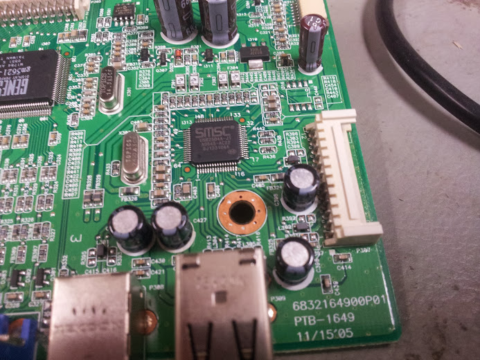
USB hub
So, this circuit is interesting, it’s a USB hub. The USB hub is entirely separate from the controller that drives the LCD except for power. I have in the past had good results tracing out the power for the circuit seen here and cutting power to the rest of the board to use it as a stand-alone hub. The thing about powered and un-powered hubs is that in most of the hubs I’ve seen is that the 5 volt power is hooked directly to the input 5 volt line on the USB-b port. The un-populated chip on the upper right side of the board is probably another one of those ubiquitous i2c EEPROMs that would hold the USB Vid:Pid pair (as seen in that older article on the logic analyzer).
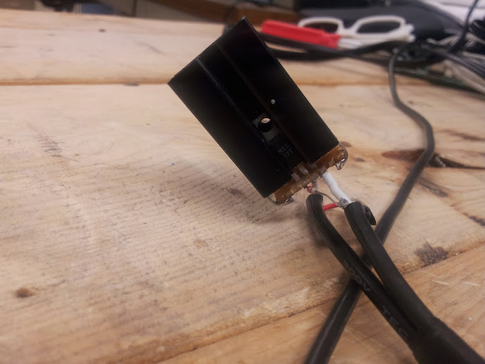
Here is the problem, the backlight doesn’t work. The symptoms are that when you power it on one of the coils fizzes and then the over-current protection kicks in and kills it. Presumably the coil had shorted, so I did the inadvisable and replaced it with an inexact replacement coil. That coil fizzed as well, so I figured there was a problem further upstream. Probably a broken FET that’s passing too much voltage or something, but I never found that out. My solution was… very hackish. I replaced the inverter with a new one. A new one salvaged from an HP film negative scanner lightbox. I don’t have pictures of that, but the inverter is exactly the came as one out of one of those blue inverter boxes from the mid 00’s that drove the ever classy blue cold cathode tubes (you know, the ones that are really shitty quality and explode periodically).
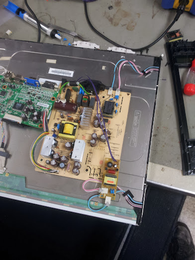
crazy solution being tested
In this picture I have removed the coil (no more arc-ing (fizzing)) and powered the inverter from the 12 volt out put designed for the amplified speakers that are an optional extra for this and most model Dell monitors. The problem is that the backlight still shut off after a few seconds. Time for some more fast-and-loose hacking.

underside of working inverter
So, without tracing out the circuit here I can see a bunch of diodes and resistors tied to the high voltage section of the transformer. The thing I can assume from here is that a network like that can be used to sense the voltage (through dividers) and waveform (through dividers or zeners) of the output of the step-up transformer. This type of closed-loop control is advisable so you can shut down parts of the circuit without blowing anything up. It is also the enemy of simple hacks like this. Let’s look at the section I modified.
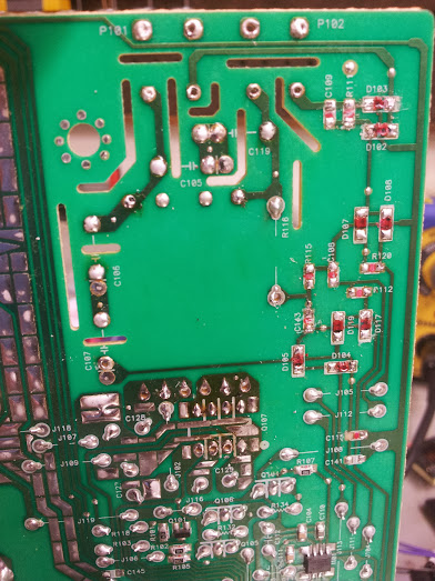
“modified” board
So, of note here is that I removed pretty much everything. The red stuff is glue used to hold the components down before they were soldered in (or maybe to take the mechanical stress off the solder). This part of the board was gutted and I assumed I’d have to feed the signal from the other inverter to the sense circuit for this one. I didn’t. It just works. Who would have figured.

you’ve had some cowboys in here…
The final configuration, complete with plastic sheet for insulation and hot glue for adhesion.
It works!
That’s it. That’s how a simple post on a “standard procedure” repair became a Frankenstein’s monster post.