Archive for August, 2019

Reviving an antique cnc router

August 7, 2019

TL;DR: This machine is very light duty as far as cutting goes, and the tolerances leave something to be desired (but it’s way WAY better than not being able to use one).  i3Detroit is currently in the middle of a fundraiser to help expand into the second half of our building, and part of that expansion involves buying some new tools that we now have space for.  We have decided that upgrading this machine beyond what I have listed at the end would be a waste as we could buy a new machine that would be more reliable, sturdier, could take bigger cuts, and is more precise for the money it would take to upgrade this one.  We are hoping to get at least $50k raised by October in our fundraiser, because if we do the Michigan Economic Development Corporation will match that $50k to help with out expansion.  Even though this machine will ideally be operating as a wood router for less than a year, it will likely live on as a CNC plasma cutter considering the side forces for that tool are pretty much zero.

20190807_211045

I am classifying this one as an antique even though I have used hardware older than this when it was new.  The cnc router craze is relatively new as far as manufacturing processes go and this one is downright archaic compared to what I am used to seeing.  It uses steel cable and turnbuckles for the drive and quadrature encoders and ball chain for feedback.  Looking at the design was kinda surreal:


I’m a member of a makerspace known as i3Detroit, many of my previous hacks have been done either in service of them or at least using their facilities.  We recently received this old CNC router for free, but the catch was that it didn’t work.  There are several reasons it didn’t work, but the one I’m tackling is the electronics.  A CNC router is no good if the computer can’t talk to it, and that’s the problem we have here.

20190807_211038

The computer we got with it is an old socket 7 box with a 2GB IDE hard drive, 16MB of ram, and a 110Mhz Cyrix 6×86.  The really odd thing is it has two BGA chips onboard, 4 PCI slots, 3 ISA slots, spots for SIMMs, DIMMs, and onboard IDE.  Happily enough it powered up and we were treated to Windows 95.  In the documentation there was talk of a licence for Engravelab and the number in he documentation matched what was plugged into the parallel port of the machine.  There were also two serial ports and one of them was occupied by a serial mouse, I couldn’t figure out which port the mouse was hooked up to but when I tried to talk out one of them the mouse stopped responding: mystery solved.  With the serial ports labeled we could now try to use the software on the machine to try to plot something on the CNC router.  That inevitably led us to our second problem: the CNC controller.

20190807_211008

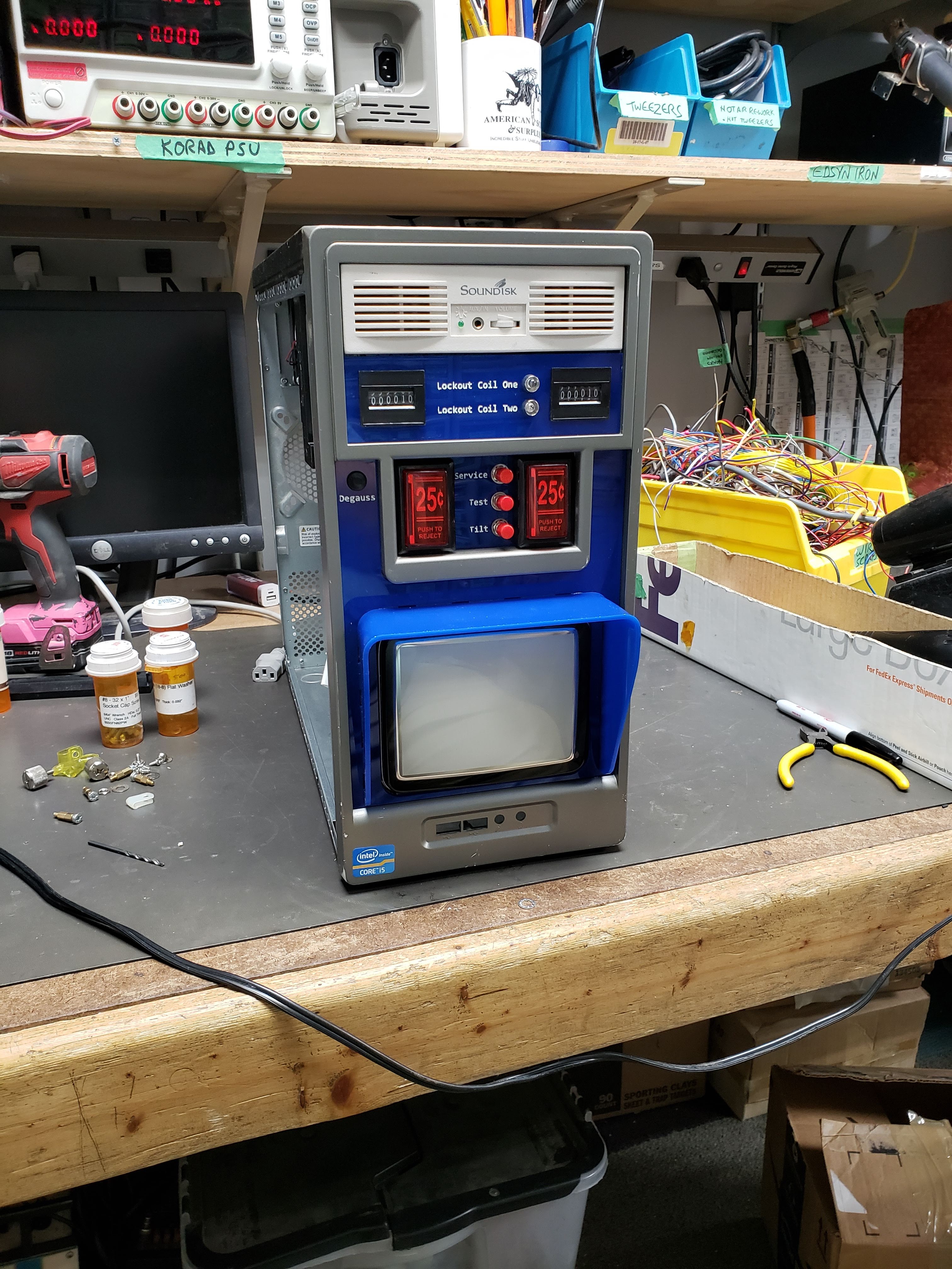
The controller for this particular machine was housed in an old AT computer case and the power supply was shot.  I have no doubt we could have brought it back, but for now we dropped in an ATX supply and I wired the green wire and a ground wire to the old alternate action switch which used to switch the mains.  We now have a functional power supply.  There are no indicators that it’s on however.  The case that was repurposed to hold this CNC controller still had the entire complement of front panel LEDs and buttons and only the power LED looked like it had been touched.

20190807_211149

Let me take some time aside here to ask, why would anyone ever need to wrap the LED and button wires in a ferrite core? is the old computer that sensitive to interference picked up by a foot long wire?  It’s not like there are fast signals running to those LEDs.  Ok, back to the repair.

20190807_211015

The power LED was burned out, but this manufacturer terminated the LED side of the header wire with a two pin polarized 0.1″ spacing jack (2 pin fan connector jack to me) and just slid the LED in.  I could see that the green LED was burned up, so I swapped in another one, added a current limiting resistor and now we have a power indicator.

20190801_192356

“We applied the cortical electrodes but were unable to get a response from either patient”

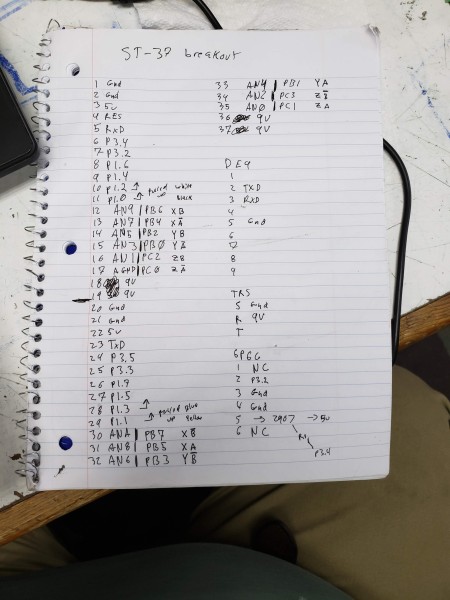
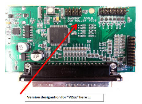
The next issue is the controller itself, It is an 80c32 dev board by Blue Earth Research called the XPLOR 32 and has a frickin’ DC-37 connector for all of the I/O and power (I love them already…).  This controller has a rom on it labeled “ShopBotControls Ver. 8 0420980000204” and from their website it seems that Shop Bot has had many generations of controller that kept this DC-37 connector.  The board it’s attached to is a generic breakout and I have pinned it out entirely along with noting where the connections to the encoders and stepper drivers go.  In doing this I noticed that the DE-9 serial port that we had hooked directly up to our PC was passed straight to the 80c32 without a level translator.  Is that cool? I don’t know but that’s how it’s wired.  When trying to connect the software to this module it would do things on the correct serial port (we had an LED indicator on it) but we got no response.

20190805_022017

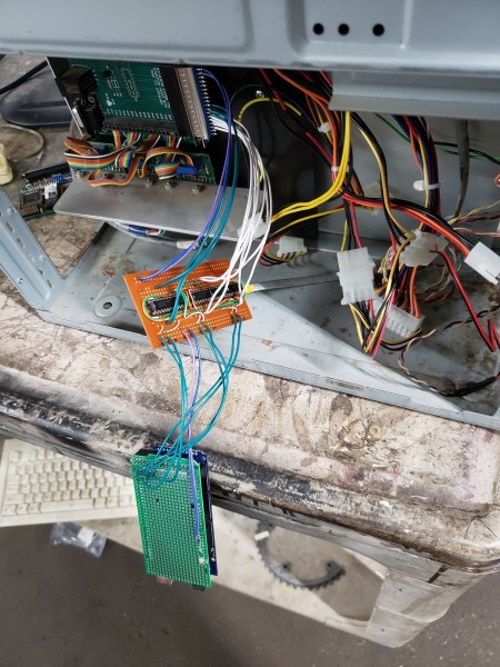
The final mystery was the stepper controllers.  They’re not really controllers, more like drivers.  The SLA7026M have virtually no smarts in them except current regulation and take quadrature signals raw to drive the windings of the motors.  This means no step and direction signals which is what most CNC controllers want to output.  This was the part that took the longest and I kept double and triple checking the wiring each step of the way.  I borrowed a design for step and direction to quadrature from this post.  Even in the initial question he’s asking if there’s an easy way to make the circuit better, but for me it’s good enough to start cutting.  I was feeling a bit brain-dead so rather than staring at it for an hour and not being sure it would work I went on logic.ly and modeled it.  I have to say, that was a very easy tool to prove to myself that the circuit would work.  I soldered in 5 sockets and then noticed that the chips wouldn’t fit that close together, so I belt sanded the chips to fit and kept on. 

ezjda

I really like how the circuit works.  You’ve got two XOR gates and two D latches.  The output of each XOR is connected to the data pin of each latch, so whatever it evaluates will get read in when the circuit is stepped.  The step pin is connected to both clock pins on the latches so every step the circuit re-evaluates and the states change.  One input of each latch is connected to the direction pin, which swaps what polarity the other pin needs to trigger.  The other pin is connected to the output of the other latch, meaning that one latch only changes state a cycle after the opposite latch changes state.  For one of the XOR gates it’s connected the the Q output on the latch, but for the other it’s connected to !Q meaning that the state changes are always happening on the opposite polarity.  The normal and complementary outputs of each latch are used to drive the full quadrature so you don’t even need not gates on the output.  I find this quite a nice and compact circuit to solve this issue.  

20190805_024220

they’re socketed, sure, but you’ll have to sand the new chip down to make it fit

With all the custom stuff done I just had to grab an arduino mega and flash it with grbl-mega, it then happily talked to me over GrblPanel.  Soldering up those step and direction wires to the shield I competed the custom electronics to make this thing drive.  Now, does it work?


Does it ever! There are of course remaining tasks to be done:

  1. Re-string the steel cable to make the X axis move
  2. Find a way to use the quadrature encoders on the X and Y axes
  3. Add endstops for homing
  4. Add endstops at the other end to prevent crashing
  5. speed control of the spindle?
  6. rebuild the spindle (bearings? brushes?)

That being said, the only thing that stops it from making cuts is the first point, so that’ll be the next one to tackle. And if I’m really feeling like a smartass I’ll put a max232 on that shield and you can use the controller just as it was originally (I think), but this time it’ll take straight g-code.

Portable arcade test rig

August 6, 2019

In working with arcade PCBs and trying to debug, diagnose, or just determine what they are it’s nice to have an arcade cabinet to plug them into.  Sometimes you want to set them up where having an arcade machine is difficult, or putting the board on a bench is most helpful.  In that case, a JAMMA harness and arcade monitor would be the usual prescription.  That is a little cumbersome to have to carry around all the time, and also can be fragile as monitor neck is exposed.  It’s possible to get a 15khz to 31khz converter to allow arcade boards on a regular computer monitor, but where’s the fun in that.  To solve this problem I packaged all the contents of an arcade machine in to a mini-ITX case and made it as portable as possible.

20190728_130455
my dumb genesis controllers can be seen in their first application

To start the discussion of some choices, first I need to go over JAMMA.  JAMMA stands for Japan Amusement Machine and Marketing Association, Inc. and is the shorthand for a rough standard based around a 0.156″ pitch double sided 28 pin long card edge connector.  I say rough because I’ve found some variations and omissions that I will try to correct on this rig as time goes on.  I don’t intend to try to make this an everything tester initially, but if I need to test additional boards that use other unpopulated (or otherwise mapped) pins I’ll make revisions.  I compiled a ‘comprehensive’ set of pinouts for the JAMMA connector based on a lot of various incomplete or different variations (I almost said universal instead of comprehensive, but that’s a brand of arcade manufacturer with their own variation):

jamma-pinout

Here’s my explanation:

  • Some things are pretty constant, the top power rails, the video connections, and the  coin, joystick, and a few buttons
  • Some things have been omitted more and more like the lockout coils,  the coin counters, and whatever power rails a particular board doesn’t need
  • Other things get extended into unused or redundant pins, like buttons replacing grounds or test switches
  • Creating stereo sound seems to have been re-invented at least twice

MGD is the arcade incarnation of the dreamcast, and I’m not planning on hooking one of those up any time soon (but if I do I know it’ll mostly work.  I do like Neo-Geo, so having those buttons work would probably be nice (maybe I can get clever and mix the sound).  The rest of the issue is to try to populate things that are usually omitted and hope I don’t run into too many crazy things.  Right now I have populated everything the JAMMA connector I used had wires for, and ordered more crimps to populate the others.  I used the common L and 10 connections for mono sound out, even though that’s not supposed to need an amplifier.  As you can see this is pretty much all you would need for any arcade machine, not even just JAMMA compatible ones.  Using this interface and some adapter boards it is possible to connect just about anything to this tester, although it may require a special adapter to be made.  Some adapters may not be passive either, Nintendo had this thing that inverted the colors to their monitors, others may use different voltages, but all this can be made to work now that most of the items are in a nice compact case.

20190805_040138
Interior shot

This lets me show the various things I’ve done to it so far.  the JAMMA connector goes out the I/O backplane hole, the DE-9 ports I have used for controller ports go out the PCI slots (the brackets already had DE-9 knockouts in them).  The power supply is a regular arcade power supply riveted through the immobile side of the computer case, it is hooked up to the back of a PC power supply that I cut the back plate off of.  That plate has the fan, power switch, 110/220 switch, and power connector on it and they all work.

2019-08-06

The monitor is a Samtron 5″ monitor from here although their prices are not accurate any more.  The monitor chassis is mounted on the motherboard tray so I can access the tuning controls, and I cut away most of the 3.5″ bays to allow my hand to get back there.  The monitor came with a degauss coil, but no associated drive circuitry, I initially hooked it up with a button, but that blew up the first coil, apparently a “positor” or positive temperature coefficient device is used to open the circuit at the optimal time to fix the screen.  I pulled the device out of an old 15″ CRT monitor that came in with a Windows 95 era wood CNC.  The monitor has inputs for RGBI (although it appears no one has ever documented actually using one for that) and was converted to analog with help of a sync splitter and this guide.

20190803_221420

Along the top in the last two pictures is a 5.25″ bay set of speakers, this is what really led me to this project, just throw it all in a PC case.  I do also remember an old website where someone crammed several small black and white portable TVs into a case and fed them with a modified video card to display at the right frequency.  He managed to drive three monitors from one signal, one color for each monochrome monitor.  Originally that set of speakers had a cord hardwired in the back, I took it upon myself to eliminate the cord and put a jack so the harness could plug into it (there was a footprint on the pcb for a jack I had).  After opening it I realized that the speakers were just grills and the real speakers were regular big 8R drivers sit at an angle and pointed up, not even any isolation between them.  There’s just this big cavity and the sound will eventually make it out the front.  Well.  If they can do that so can I.  We were looking for a design to fit the blankout plate that is to go over the USB and sound holes when I pointed out that the Vault Tec logo is about the right proportions.  That plus blue meant that it now needs yellow instead of white paint.  At the insistence of Mike who pointed out that it looks great, except for that crappy speaker grill, I decided to just bandsaw off the front and he’s make another acrylic piece that went all the way up.  Along the way I decided to eliminate the power indicator and the aux-in jack and switch to a more appropriate knob instead of a slider.

20190805_040143

As you can see we borrowed a speaker grill off a thing and a knob off a guitar (it’s mono now, but it drives both speakers) to make the top audio section.  The text around the knob was cribbed from an HM audio generator.  The arcade coin buttons happen to perfectly fit in the floppy drive section and you can see the degauss button that’s actually bolted through the steel so it sits flush.  I bought real coin counters and added diodes to them to protect the arcade board, they are apparently low side drive so I hooked mine to the 12v line since they’re 12 coils.  The lockout coils I knew less about, I just assumed they’d go high with 5v and wired the other side of the LED to ground, but we’ll see once the terminals get here because that section wasn’t wired on this harness.  I added Tilt, Test, and Service switches even though Test wasn’t populated on my harness either.

20190805_040828

I gave this thing a new coat of paint in almost the same colors it was already, just to cover up the scuffing that had gotten done to it over the years.  I still have handles to mount, additional pins to wire, and maybe a circuit to sit in the harness and talk to buttons 4, 5, and 6 after decoding real 6-button genesis controllers.  I also blew up the audio amp chip on the tetris board, oops.  Did you know that tetris by Atari has two power amp footprints on the PCB and only one populated? The schematic seems to imply that they are in parallel but I assure you the footprints are mutually exclusive.

EDIT: the tetris problem was because that mono output was supposed to be for an isolated speaker and I’ve now put a 1:1 audio transformer in the line to isolate my amp ground from speaker-.  Also some boards assume all the power and ground pins are hooked together in the harness, this isn’t true in mine yet but I added one bodge so far to bring up one board.  I may use vampire taps to join the remaining wires.

We picked up a jamma extension harness from china for super cheap, so far I’ve had to fix a bunch of stuff:

  • 12v was run with one wire and only connected to one side of the fingers, but both sides of the card edge female
  • 5v was run with one wire and only connected to one side of the fingers (two fingers), but both sides of the card edge female (all four pins)
  • -5v was not run
  • coin counters and lockout coils were not run
  • no key in female card edge
  • 7th pin not cutout of fingerboard

I can understand cheaping out by running fewer wires, and I can understand not using the coin counters and lockout coils.  The lack of -5v really shows that this was designed for a small target market.  The lack of joining the finger sides together also shows that it’s only really meant to work on ‘most’ machines.  The lack of a key and cutout, I don’t know any boards this would work on out of the box… That all being said, The cost of this harness was under $5 and well worth it after repairing it.

Further Edit: I drilled and tapped some holes and bolted some feet to it, these come from some old test gear and really help the viewing angle of the CRT if it’s sitting on a desk.