Archive for the ‘projects’ Category

AMC Eagle hatch repair

July 29, 2020

This is a combination fix, I decided to replace the hatch struts so I didn’t have to haul around a stick to hold it open.  That necessitated making sure I had quality hinges and replacement hinges if they failed.  When I got the hatch off I found out why the defroster didn’t work and fixed that.  While it was off I decided to clean up some rust and re coat the metal for protection.  Finally I have touched up the primer in what should be a match to the original paint.  Eventually I need new weatherstripping.

Hinges:

I got two sets of hinges from the AMC Eagle’s den facebook page.  The first one had a single usable hinge (pitted) and one cracked so badly I don’t want to install it ever.  The cracked one has experienced the hinge pin rusting so that it expanded and cracked the zinc casting.  This exact failure mode can be equated to old restorations of the Parthenon.  The second set was mostly perfect except I had to clean off some silicone that I assume a previous owner had used to seal around the body.  The set I had on had one good hinge and one that had been welded back together and was porous and cracking again.  I am certain that this one would have broken under the stress of new struts.  I now have a backup set should my good set fail and a set that I really shouldn’t sell to anyone nor use as molds for casting.  I have also noticed that the rubber seals that sit between the hinges and the vehicle are specific per side, but I don’t know why.
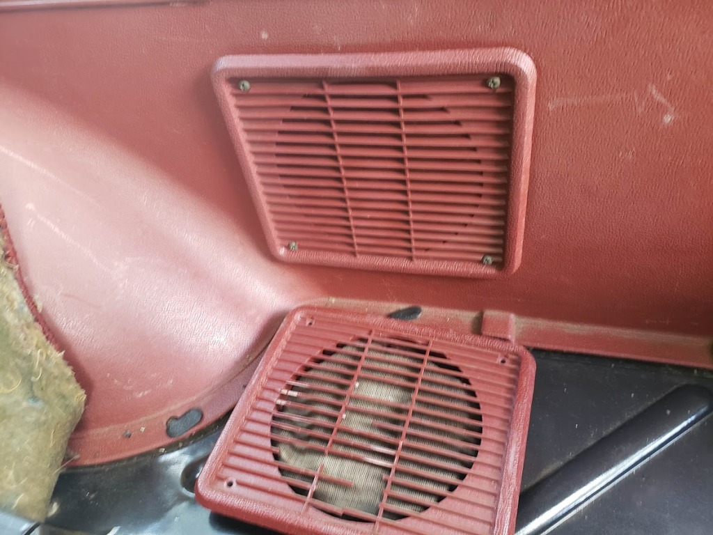
Good one off car
Strange matte finish with crack and porosity
Good part
Welded/repaired part
Pitted part
Cracked part
Silicone sealant residue
Right one has this raised bit
Left one is flat

Defroster:

This one I noticed when I got my thermal camera.  The defroster doesn’t work.  I found that the cable which holds the ground wire from the defrost panel was cut because it was not routed correctly through the hole in the trim.

I see a cut in that shielding
Oh, there’s the grounding strap.
I grabbed some silicone insulated wire for flexibility and doubled up on the strands for current carrying capacity
Insulation was pieced back together and taped together , hopefully this can be routed properly and not break again.

Rust:

On the bottom of the hatch there was some serious rust and some effort to paint over it (which was flaking off).  I decided to take it all the way down to bare metal with my wire wheel and protect the surface with rust converter (converts rust to magnetite which does not propagate and is fairly hard).  Once I am sure that there is no more rust I topped it with self etching primer to really try to bond to the metal.  I also found a portion of the body around the plastic alignment peg hole had some rust creeping under it.  To get it off I had to use a phillips bit and my new manual impact driver.  The wonderful thing about that is the force that is imparted to seat the bit in the head also breaks loose the rusted threads.  This avoids stripping the head of phillips screws.  After all this the primer will get covered with some Mist Silver matching paint and everything should look better than new.

Rust and some lazy black paint
Wire wheeled to bare metal
Painted and reinstalled (this will need either a new gasket or RTV after painting)
Primed along the whole bottom edge

Struts:

These I picked up off Amazon.  It’s a shame to see the old ones go because they’re so beautifully engineered.  I particularly like the latch mechanism that keeps the ball retained in the socket.  I assume the AMC logo on them either indicates they are original or at least that they are OEM replacements. The modern style retainers use spring steel curved to wrap around the outside, and the housing body is plastic. The original style is shown below. The ends are interchangeable as the ends of the strut are male threaded and that thread has remained consistent over many decades.

New struts with new style retainers
old style retainer detail
new struts, old ends

The last thing I want to say is this: whoever designed the hatch lifting mechanism/geometry is both wonderful and terrible. They designed it to be maximally useful and so that the struts are not in the way when the hatch is opened. The consequence of this is tremendous force required by the struts and the stress it puts on the rest of the system. Particularly the hinges. I love that they specified such powerful struts to overcome the massive mechanical DISadvantage based on the geometry. I hate whoever designed or specified the alloy for the hinges. They’re cast and polished zinc, yet they have to carry such a portion of the gas struts’ force trying to rip them apart at all times. I took a side view shot so you can draw some diagrams of forces and puzzle over it yourself. Good idea, I commend them for that. Poor execution.

could you get less mechanical advantage out of this design? I doubt it.

The home page for this project is here, it has a link to the album of pictures.

AMC Eagle Rear speaker installation

July 29, 2020

When I was working on the rear hatch I decided to take a crack at the rear speakers and grille.  I researched replacement speakers that would fit exactly for a while and came up with Rockford Fosgate R1525X2 Prime 5.25-Inch Full Range Coaxial Speaker – Set of 2.  I bought two sets (for the front door speakers and the trunk speakers) but will be installing the front ones later.  If I recall correctly these speakers are specifically shallow enough to be install-able in the front door without hitting anything.  I also thought there was a different speaker above the glove box but I believe that is if you have an AM only radio and it is a mono speaker.  I will eventually get a dual coil one of those speakers for my ’57 Chevy, but it looks like I don’t need it for the AMC.

The first thing I wanted to do was replace the speaker grille, so I bought one from ebay for a dissapointingly high price and when I went to install it I decided to do the speakers at the same time.  The speakers are not centered on the grille hole, which is a bit confusing at first.  

why? just… why

The old speakers have spaced connections at the same interval as the new speakers, but the new ones have one 0.187″ spade connector contact and one 0.110″ whereas the old ones are the more traditional 0.250″ size.  I made an adapter harness to break them out to the older standard spade terminals.

New speaker installed in the plate, old torn speaker being replaced is torn
New speaker with jumpers and old speaker for comparrison

The home page for this project is here, it has a link to the album of pictures.

Scanning Electron Microscope repair – CA3098E replacement

February 2, 2019

So, a buddy of mine just picked up an Amray SEM.  I have no idea what model, but apparently there’s a mailing list community of hobbyist and they’ve never heard of this particular model.  That’s a good sign.  After trying to set it up several problems were found and fixed (I’ve got to start documenting things again) we came across this poser.  There are four thermocouple inputs on the board, amplified with some opamps, and that signal is piped to a single display (galvanometer) via some analog switches.  None of that interfaces with the microprocessor, except for the fact that all four analog signals (post amplification) run into four of these CA3098E hardware hysteresis chips.  Simulating a signal for the thermocouple using a 10 turn potentiometer and a AA battery we found that the hysteresis chips were not doing what they should.  The datasheet is pretty clear that there’s a high and low setpoint, and input and an output, and the output was not changing when the input went above or below the setpoints.  We really didn’t have a way to tell what else it should be doing so we declared them bad.

With no source for these chips other than some from e-bay which were probably salvage anyway we resolved to build a replacement.  The first thing that came to mind is using a literal textbook as reference to build the textbook op-amp hysteresis circuit.  There was a problem with this approach: despite thinking we came up with the right equations it did not simulate right in LTspice.  In the end it ended up that comparators are different than opamps in ways this circuit cares about, but it only took like three hours to figure that out.  The problem I had with that circuit was that it only used one setpoint and some carefully calculated resistor values, I’d rather it be a real drop-in replacement for the original chip and take the two setpoints that the board has trimpots for so it could take the original chips if we come across ones we want to use.

img_20181223_001103

Matt’s circuit, smaller but requires a different setpoint and if you want to change it you have to recalculate those resistors

My circuit is an example of brute force in electrical engineering.  No calculations, no carefully picked resistor values, just building blocks.  Problem statement: we take one input and two setpoints, switch the output high when the input goes over the first setpoint and the output only goes low when it goes below the second setpoint.  The output of the entire circuit is open collector and can be pulled up to whatever the output wants, which is useful for someone working with chips that are basically only good to 5v.  To me this sounds a lot like an SR latch, you set the output high with one pin and reset it (set it low) with the other.  You can build this latch out of NOR gates, I used NAND because we have buckets of 7400 chips I wanted to use up.  To drive the 7400 chip I needed a 5v rail derived from the 15v that drives the chip.  Rather than using a linear regulator which would burn a lot of that as heat I opted for an off the shelf buck converter hardwired as a 5v output (the practical upside of which is that there is now a usb port inside the machine if you need it for anything).  The comparators that drive the input of those are an LM339 (good to 15v) and I used three out of the four in the overall design.  The output of the latch is used to drive that third comparator which is compared against a resistor divider making half of the 7400’s power rail so it simply follows the output.  This buffer is to give the output of the circuit an open collector output as the 339 is just that (I’ll have to remember that trick when interfacing with different voltage systems).

img_20181223_115557

My circuit, bulky but perfectly replicates the subset of this chip that we actually use

The final design goes like this:

Input goes to one input on comparator A and one input on comparator B

setpoint A goes to the other input on comparator A

setpoint B goes to the other input on comparator B

15v drives the comparator and the buck converter to generate the 5v rail

comparator A and B are the inputs to the 7400 SR latch (pulled up to 5v since they are open collector)

5v rail is used to drive the 7400 and generate the 2.5v reference voltage

one of the outputs of the SR latch goes to comparator C

the 2.5v reference voltage goes to the other input of comparator C

the output of comparator C is the output of the circuit (pull up to the right voltage is on the PCB we’re interfacing to

This circuit is a real challenge because you can flip the polarity at basically any point, and I have purposely left out any mention of which is correct because I don’t remember what I did but at one point it was wrong and at another point I fixed it somehow.  You also have another two NAND gates to use which can be used as NOT gates if you don’t want to swap the inputs on a comparator you wired wrong.  This is an interesting project for using analog and digital components as well as interfacing to an existing circuit without using any programmable parts.

bttf3

Yeah, my fix is kinda like this

AMC Eagle Dome light LEDs

October 16, 2017

So, I feel like an idiot.  I also feel like I’ve done this before.  I mean writing this, so forgive me if this is a duplicate post, but when I tried to point it out to someone I couldn’t find it.  I had a perfectly working dome light and I made it slightly worse, and slightly better.  To remove this light there is a plastic cover that is very fragile.  mine was perfectly intact and I got it off and on several times… before breaking it in half.  I would have had it done too, had I not made the lower bone-headed moves.  Once that cover is off you can remove the two screws from the roof, remove the spade terminals on the back, and finally un-clip the plastic from the metal.

I recommend these solder joints

Here is the inside of my dome light.  You can see the discolored plastic where the bulb heat has done some damage over time.  You can also see how I have added LED bulbs here.  I also added some solder to the riveted joints to prevent them from being high resistance joints in the circuit.  The side bulbs have the correct polarity, but the middle one you have to try both ways before you know you’ve got it right.  That LED I needed to modify because it came without those two metal ends.  The light bulb this emulates has two loops out the glass and I stole the caps from my old bulb.  That connection plus the fact the loops on mine were steel and not copper made for a terrible connection to power and a very intermittent light.

so much tree spooge

Grungy but it works, I added tons of solder to firm up the connections on these joints (and got a little silicosis from grinding down the PCB to fit inside the covers).  That works, reliably, every time.

I was going to replace the switches because they felt sloppy (felt like the metal cage over the slider was coming off) but I found they’re actually fine and after cleaning them they went back together smoothly and operated that way as well.

beware stress hardening the metal

Ok, on to the part that makes me an idiot.  Start with the questions I didn’t ask: What lights are in the dome light? when can they be on? when are they commanded to be on? how many wires does that take? how could they do it with fewer wires?  The Map lights can be on at any time, the dome light is on when switched on from the switch to the left of the steering wheel or when the door is opened.  This means that the dome light is switched from the dash board area and the map lights are switched at the light.  The map lights need an always on power source and ground and the dome light needs to be switchable.  Rather than sending 12v and switched 12v  with a common chassis return they sent a 12v and switched ground while also using a chassis return.  I was not expecting that.  I was not expecting that so much that I instinctively jumpered what looked like two ground connections and when it was all installed it acted like a door was open.

My shame (do NOT do this) from top to bottom is 12v (spade), switched ground (spade), chassis ground (screw)

I was so used to switched power and constant grounds that when I tried to test this on a bench I found that the map lights didn’t work.  I was applying power to the two spade terminals and got no map lights.  When I discovered my error I did not realize that it worked before I took it apart and would probably work once installed.  I determined that I would improve it by jumpering the grounds together, and it all worked great.  Until I put it in the car.  Once I connected the grounds together this made it seem like the door was open all the time, providing a path to ground that an open door was supposed to.

By the time I realized my error and corrected it I had broken the dome light cover.  I decided to buy and modify a Ford one because I had heard it was possible.  I determined that it needed to be bent slightly around the metal case.  I fucked this up too.

extra shame

the plastic bubbled under the heat gun and almost didn’t move at all anyway.  I used to be good at this, I swear (this is where I insert the middle school plastic heat bent project that also had bubbles showing I was never good at this).

That’s it.  I taped back together my broken cover, stuck it in, and am done.  now I have a melted aftermarket ford part, a cracked OEM AMC part, and some LEDs to replace bulbs that weren’t burnt out.  Is this a win?  The home page for this project is here, it has a link to the album of pictures.

AMC Eagle reinstall bumper trim

August 16, 2017

It got hot this summer.  Not hot for places that usually get very hot, I’m not talking death valley hot, but hotter than a healthy planet should get.  This caused my rear bumper center trim to fall off.  When that happened I found out it was held on with a variety of sealants, all of which were fairly weak in the heat.

Before, you can see some of the adhesive along the top edge

Taking off the drooping trim I found blobs of silicone, and a much thicker and more tar-like substance.  Using plastic razor blades I was able to get off some of it, but if you’re very careful and use only brand new metal razor blades then you can get off the material much easier and faster without hurting the metal.

A drooping problem that no pills can fix

Once cleaned up on the bumper I turned to the trim itself.  The adhesive was very strong and uneven.  It seems if this had stuck to the bumper as well as it stuck to the trim that there wouldn’t be a problem.  As it turns out it stuck to dirt and twigs pretty well which did not help the situation.  I used degreaser, soap, grill grate scrub brushes, brass and steel wire brushes to get off all the bits of adhesive.  In the process I scored up the back pretty bad but that doesn’t worry me too much since it will now sit flush on the bumper.

Clean bumper ready for install

For installing the trim I used 3M 03614 Scotch-Mount 1/2″ x 15′ Molding Tape and put two strips along the metal bumper before peeling the protective coating off.  I don’t know how well this will hold up over time, but I’m willing to change it should it fall off again.  I would recommend using a roller to ensure good adhesion as this type of tape will very quickly adhere to dust or anything in the air and if you go to press it on later it will never stick in that spot.  I would also recommend centering it as there is now a sizable gap on the passenger’s side of my car.  I suppose these need room to expand in the heat.

A little to the left…

The home page for this project is here, it has a link to the album of pictures.

AMC Eagle license plate holder refurb

July 28, 2017

I hate rust.  It slowly eats away at the things I hold dear.  Now, for another permanent solution to a temporary problem, let’s de-rust and paint the springy license plate holder!  My favorite tool for this is the sandblaster, there’s a chemical called evaporust that I will be covering in the future but for now let’s mechanically strip this part.

like night and day.  

I like how this process clearly shows what the un-tarnished metal should look like so you know when you are done.  Getting in the nooks and crannies is a bit tiring, but it will be worth it to not have the rust come back.  After wiping it down with solvent I screwed it down to a back board to get paint under the sprung bit.  This took several coats and several different mounting methods to get complete coverage.

spread eagle and covered in white…

Once the paint is dry I used rubber cement to attach the rubber strip along the top to protect the plate.  I have plastic inserts on the bottom for machine screws to fit in, but the top ones have gone missing which is why mine is held in by stainless bolts and nylon wing nuts.

doesn’t that look better?

I took the time to clean the area around it with a nylon scrub brush, a green/yellow sponge, and some soap.  I think it looks a lot better now and I just keep telling myself if I do this one piece at a time I will eventually have a very low maintenance ride.

lookin’ good

I have had friends tell me they recently found out where the fuel filler is in a ’56 Chevy, or that older cars used to have them behind the license plate to which I surprise them by saying that my car does that.  I’m not concerned about removing my locking gas cap because the location of the filler on this car is almost as much of a deterrent to gas thieves as if it were three on the tree and they were car thieves.

The home page for this project is here, it has a link to the album of pictures.

AMC Eagle license plate light fix (LEDs part three)

June 23, 2017

In my endeavors to make everything on this car an LED I have decided to replace the licence plate light with an LED (a spare dome light).  All the documentation I saw said to replace this part ‘as a unit’ but they clearly have never met me.  This part is not the easiest to upgrade, but I did it anyway.

It fell apart after I opened it

After taking a dremel to the seam I found that the old heat-damaged plastic broke clean in half.  The bulb was so long ago burned out, but the goop that stuck down the spot welded leads was still soft.  I dremeled it off to scuff up the pads I could solder to and epoxy-ed back together the base.

Always use a backing you don’t mind will stick to the final product, that board would be hard to fit in the car

I let that cure overnight because I didn’t read that I had bought knock-off JB-quick instead of knock-off JB-weld.  The next day I cleaned up the edges with a dremel and removed the STEEL wires from the LED module.  Those are not copper, don’t notch your nice diagonal cutters trying to cut them in half, desolder them with liberal use of flux and heat.  The LED module was balanced on a pile of copper wire stiffened with solder and a ground wire added underneath.

Make sure to center it or you will hate it later

I then gooped many coats of epoxy under the LED to build up the post that isn’t quite tall enough (BTW, you made sure it would fit in the lens, right?) and built up a second column to support the LED module.  When that was dry enough to work I inserted the base back in the lens and slowly added layers of epoxy to make sure I got a seal all around.

Remember to label the pins for positive and negative, mine are labeled but backwards so doubly unhelpful

Sanded down the sides so it was flush-ish and would fit back in the hole it came out of.  Now I have another lamp I should never have to replace, there will be a picture of it here after I finish painting the newly blasted license plate holder.

there, nice and bright.  Forever.

The home page for this project is here, it has a link to the album of pictures.


AMC Eagle Air cleaner vacuum actuator

June 9, 2017

In my first post I noted that the pop rivets that held one of my vacuum actuators in place had broken so I taped it back on for the ride home.

Mystery part, janky fix

The advice I got from the forum was: “The thing you taped in place on your air cleaner is part of the TAC system, I believe.  That vacuum motor controls a trap door that should close when the engine is not running, I assume to control escaping vapor.  As long as it’s open your car should run fine.” which makes perfect sense.  That trap door springs shut (plastic flap, not a metal coil spring) normally and seems to be pulled open when the engine is running.  I tested the actuator (yes, I sucked on it) and it seemed fine so I thought I’d mount it back with some sheet metal screws to make the repair a bit more permanent.  Problem is, those holes are really big for sheet metal screws.  If I thought I would keep this air cleaner forever I would have tacked captive nuts on and bolted it back, but I don’t.

New rivets, new hose, all better

My fix was to use pop rivets (what a concept!) but I didn’t have the right size so I stacked some #6 washers to make up the gap and thickness.  I think it worked ok, but it also let me see how rotted the hose was so off I went to buy a roll of that.  The new hose was not the same ID so I also got some cheap hose clamps.  When I was all done I realized that I failed to slip the actuator around the bit it pulls on, so I had to bend it a bit to open it up and bend it back to close it around the rod sticking out of the door.  This is not a fix I needed to do, I could have plugged the hose and removed the door, but for now at least I know what it’s for and I have more hose and clamps for when more of it crumbles.  While I was in there I cleaned out the air cleaner, and wiped down/wire brushed everything I could get my hands on.  I will sandblast and spray this all later but for now I just wanted it back in place.

The home page for this project is here, it has a link to the album of pictures.

AMC Eagle electronic flashers

June 9, 2017

When I did my headlights I also did the turn signal bulbs… which broke my flashers.  The LED bulbs just don’t take enough current to trigger the mechanical flashers and the lights stick on.  I could have added ballast resistors to make the flashers work, but if I don’t then technically my car is more efficient.  That, and if I want to put regular bulbs back in (or someone else does) then it will still work.

Where, oh where, is the fuse block?

The thing I thought was crazy is that I saw zero pictures anywhere for how to access the turn signal flasher.  I couldn’t find it in the service manual, in the forums, or anywhere.  The Eagle has two flashers, one for the turn signals and one for the hazard lights, which is fine.

There it is! (yours may not have a janky extra fuse, this is probably for the old fog lamps)

The fuse block has two curved indents that look like they’re designed for flasher units, but only one is used.  The explanation I got and makes the most sense is that it was designed that way, but the turn signal noise was too quiet and they moved the turn signal flasher up into the dashboard to make it more audible.

Step 1, loosen those screws and pull this out

The flasher is behind the 4×4 switch to the left, and it should be easy for someone with smaller hands than me to get in and out (I did it, but the car took its pound of flesh).

There you are!

When installing electronic flashers remember you need a ground wire (I saw some solid state ones without it but I wanted a click), luckily there was a ground lug nearby that worked perfectly.  I extended the ground wire on one of the flashers so it would reach somewhere easy to install and once it was jammed back into the spring steel bracket grounding that wire was easy.  Before you do that, however, make sure your polarity is right.  I bought polarity sensitive electronic flashers (they make a polarity agnostic one but I was cheap, or maybe they only had one in stock) and the car was wired backward for them.  The mechanical flashers just heat up a bimetalic strip so they go both ways, but my new units are a little less flexible with which terminals are ‘exit only’.  The turn signal flasher was easy, jam a pocket knife in the spade connectors, swap positions, make sure to bend the tab back, and you’re golden.

purple, the universal color

The one on the fuse block was more trouble.  I decided that I would rather make a short jumper that swaps the pins than get in there and swap them.  One day I will have the seats out doing the carpet and then I will surely fix the wiring in the block, but for today this was fine.

The home page for this project is here, it has a link to the album of pictures.

AMC Eagle LED marker lights (LEDs part two)

June 9, 2017

This is a small post, but I think an important one.  I had no idea how to safely get the marker lights off my car.  I didn’t know if just the lens came off, if there were screws under it, if the previous owner had glued it on.  This is another thing I couldn’t find in the manual, they all just said ‘take them off’, ok but which part?

The whole thing comes off

On my vehicle this was stuck on so bad I thought maybe there were more screws I couldn’t see.  Of course now that I saw this it seems reasonable, but I can never be sure on these vehicles.  The LED light is polarity sensitive (what, four diodes would kill you?) so be sure to install it the right way around.  I have heard of a way of wiring the ground for these lights to the turn signals so they flash with the turn signals, but to do that with LEDs I’m pretty sure you would need a bridge rectifier.

Obviously I’m cleaning this

That’s it, really.  I just wanted to write down, somewhere indexable by google, that to change the marker bulbs you remove the screws and pry off the whole unit with the foam rubber seal.  The bulb socket is a quarter turn one and the bulbs are those flat ones that have really shitty bent leads as contacts.

The home page for this project is here, it has a link to the album of pictures.