Back in the day when I was at college we had a RapMan 3d printer. Do not buy this printer. The version we had was flat-pack, made entirely of acrylic sheets sandwiching smooth rods for construction. Staying up all night to get the first print got us a small ABS plastic cup and a rain of nuts, washers, and bolts. If you tighten anything down enough to not shake itself apart you shatter the acrylic, and the controller is proprietary, so there’s not much you can do to it from that front. We spent the first few weeks designing and printing replacement parts for the printer out of ABS because the acrylic was garbage. The extruders were nice, but used a custom machined razor sharp worm gear that would just chew up material if it was too soft. On top of all that, it didn’t have a heated bed. If you’ve ever 3d printed something you’ll know that a heated bed is quite nice and helpful to get good looking parts. Since we couldn’t interface with the damn proprietary controller we just built a stand-alone one.
We built this in one night, and to my knowledge it never got changed. This is both a blessing and a curse. If you half-ass something and it works ‘well enough’ people are not motivated to make a better one, this could mean even more time before you have a reasonable solution to the problem. If the solution is truly good enough then it’s not an issue, but there’s a spectrum… The other thing worth noting is if someone decided to take a ‘good enough’ solution out of order and replace it with an un-finished ‘right way’ solution taking the functionality from 60% straight down to 0%. These sorts of ‘fixes’ are the hardest to come back from because it involves either finishing someone else’s project, starting over, or putting back the first solution. I would tend to lean toward the latter of these options, but that’s not always possible if the parts have been cannibalized in the course of making the whole system non-functional.
Being built in one night it used what we had lying around, in this case an original msp430 launchpad. These had a bunch of features, plenty of reasons to like them, and most importantly an arduino abstraction layer ported to them. Arduino may have a bad IDE with very few features and a convoluted system of adding boards and other support, but the important part is that it’s easy enough to get working fast and has enough of a community that making your first few projects work is super easy. At the time when I documented projects it was on the IEEE Lab Wiki, considering that’s who it was built for and where people would look for documentation on how to use it. These days I’m going through my google photos looking for something to document, not to bulk out the number of blog entries I have, but just to put together a repository of my knowledge. I’m not planning on getting hit by a bus soon, but I bought my own house and am already not that healthy of a person. Here is the excerpt from the wiki article I wrote:
Overview
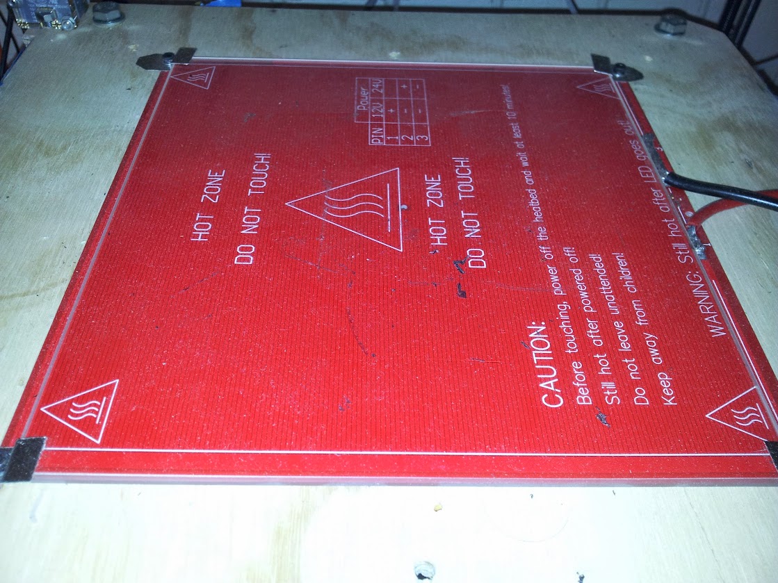
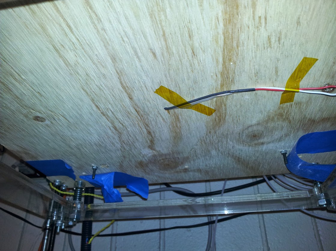
The heated bed was purchased to increase the quality of 3d prints on the Rap Man. It is constructed from a bed from RepRapDiscount, borosilicate glass from Lulzbot and our own custom controller built from an MSP430g2553.
Specifications
Maximum Build Dimensions
- X: 214mm (~8.5″)
- Y: 200mm (~8″)
- Max Temperature: 110°C (230°F)
- Power Requirements: 12V @ 8.5A
Design
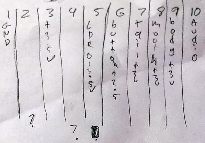
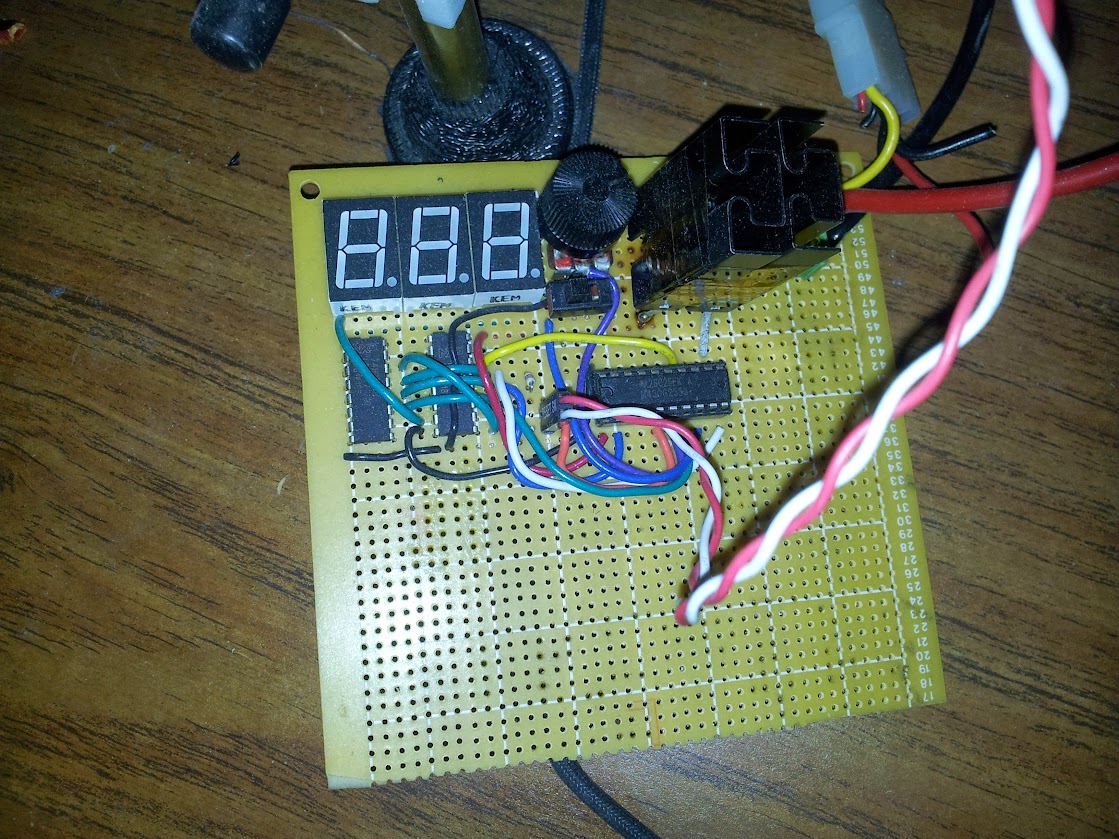
We wanted to use one of our launchpad MSP430s, but we wanted to do it fast, so rather than learn how to use TI’s IDE (we tried, there were major problems that varied between chips) we used Energia. Using some KEM-5161BR (common anode) 7-segments driven by 2 74HC595N shift registers. To conserve pins we configured the 8th bit on the second shift register to control the third 7-segment as either blank or display a “1”. We have the POT being read on one pin and the thermistor set up as a voltage divider on another pin. The FET (2 in parallel since we needed more current) hooked up to a digital output. The code is [[1]here].
Future Modifications
- Replace the thermistor table with a function
- Replace the on/off functionality with a PID controlled PWM
- Move the FETs to a separate board (or further away from the pot
- Replace the FETs with one rated for the current
- Print a PCB
I’m actually not going to elaborate on that because I don’t remember anything else about the design, construction, or functionality. Looking back, my favorite part of the code is the comment “fitted graphically”, I think I’ll use that at work some time as justification for data. On the subject of ‘future modifications’ I’m pretty sure none of that ever happened, although at least one person got burned by the FET (that really should have been a relay, way higher power with basically no heat). This article’s ‘value add’ can be my story and perspective on the whole situation I guess.
pictures are hosted here
code (and an unbuilt board design?) is here
original wiki article for the lab is here