Having purchased and actually listened to some of the new Gravity Falls vinyl, I realized my turntable needed a reversing switch (some of the audio is backward). That should be easy enough, wire up a double pole double throw switch as a reversing switch and get it to run backwards (also a center off position). I also wanted to get this turntable to work at 78RPM, but that seemed harder so I left that idea aside for now. I was actually wrong on both counts.
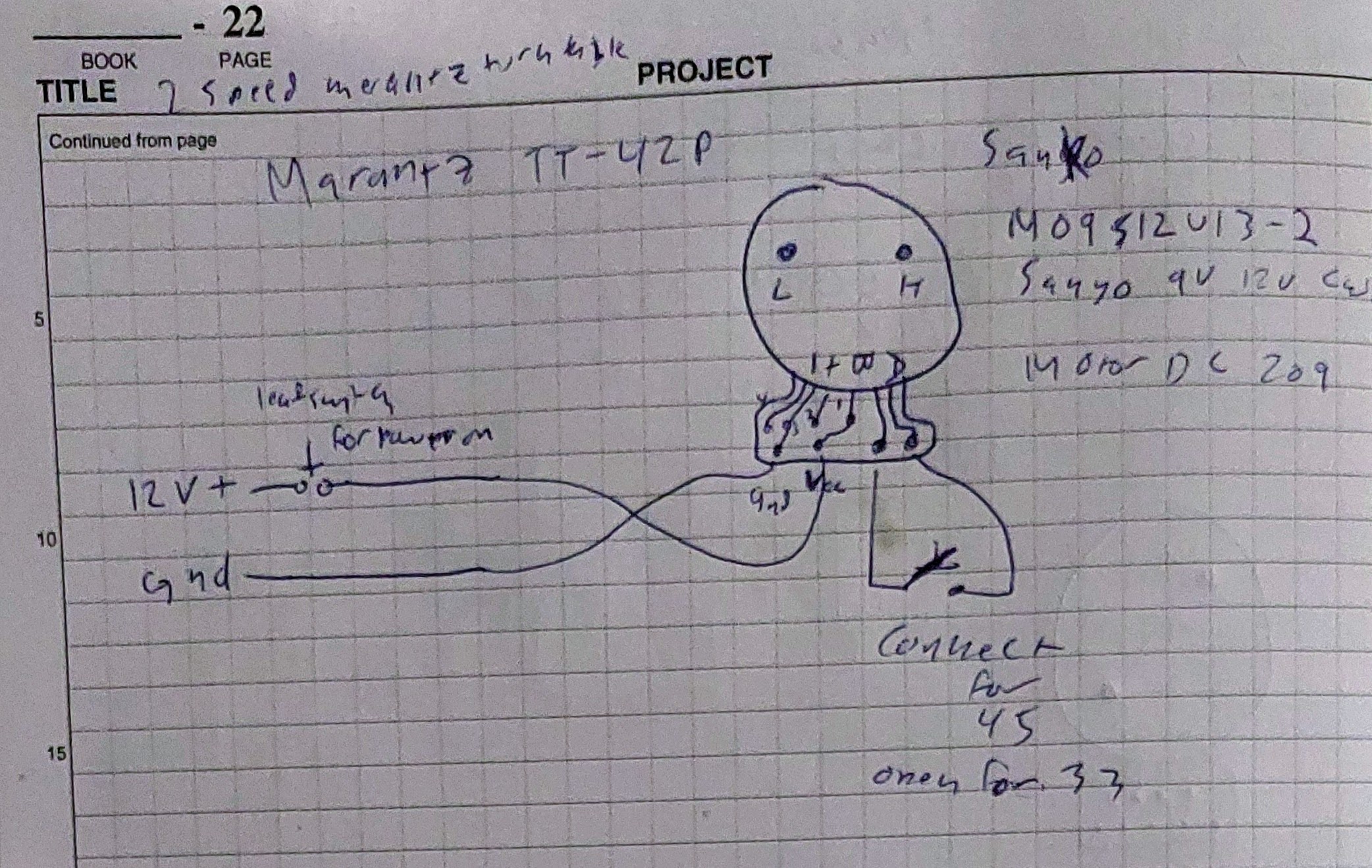
This is what’s inside the turntable, aside from the preamp this is it. The motor is a Sanko MO9S12U13-2 9v-12v cw (clockwise). That part number is of course obscured behind a giant sticker that says Motor DC 209 which is Marantz’s attempt to make repair harder. The motor controller on that board is an AN6652. This has seemingly completely flummoxed any chance of reversing it (I may come back to that later) or changing the speed. I found a youtube video that has some… interesting camera work, some forum posts, and other information that led me to believe the “-2” in that part number means 2-speed. There exist 3-speed versions, and while I might be able to upgrade this one to 3-speed, I thought it better to just but a motor from ebay.

I bought a motor (eg-530sd-3f) with wiring harness so I could use it to double check the polarity of everything. This part is from an ION iLP and the manual for that leads me to believe the labels for the switches it came with. The youtube video referenced earlier is what showed me how to wire this motor for 78RPM, that is connecting a ~330 ohm potentiometer in between the motor pin and the switch pin. I ended up using a 500 ohm 10 turn pot for that.
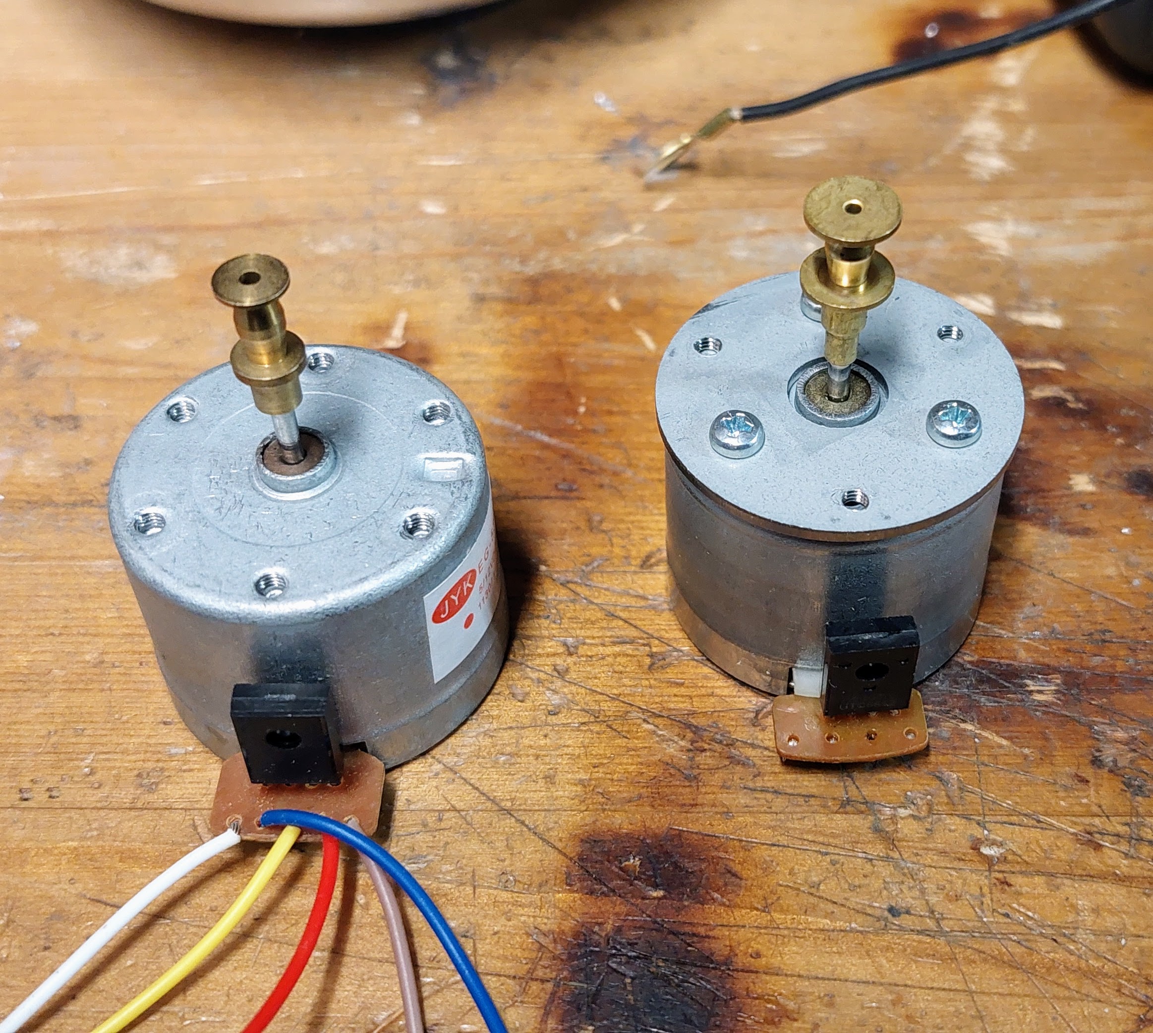
My original motor is on the right, the new motor is on the left. The spindle is a little different, but not enough to care. The funny thing is my original motor has an adapter plate bolted to it because the mounting hardware for this machine requires a motor with tapped holes at a slightly wider diameter than the Sanko motor. My new motor actually has that pattern already. Perhaps that’s why my original motor had such huge flanges, maybe the belt was mis-aligned because of the extra spacer.

Originally the 33/45 RPM switch did two things, it closed a contact for the motor speed, and it moved a linkage so the auto-start functionality would move the arm to the right spots for a 12″ record and 7″ record respectively. I actually have a situation where that is incorrect, so I removed the wires from this switch and will be adding a new one for speed and leaving this one for diameter.

Before we go any further I’ll let you look at this monstrosity. For shame, Marantz. Ground should not be red and 12v should not be black. I fixed it on both this end and on the barrel jack end, but holy crap is this dumb.

This model did not have any sensible way for you to adjust the speed so I had to punch a hole in the bottom to expose the adjustment pots on the motor (rough work, but it’s on the bottom and it’s OSB anyway so whatever).

The 78RPM adjustment pot got installed in a sensible location to start with for live adjustment while it’s on a table and level.

This is me playing my only 7″ 33 1/3 RPM record in the stereo cabinet I refurbished. You can also see the Audio Technica AT-SLIPMAT-UKR platter mat I got as a gift. I used the switch that came in the harness from ebay and carved a hole in the record player plastic cover and glued it in there. The original switch got relabeled with diameters and the new one is labeled with speeds.
A future upgrade might be that reversing switch I talked about but that would involve popping the bottom off the motor, cutting some traces on the board and wiring it for clockwise/counter-clockwise operation. I’m hesitant to do that because this player is so ‘automatic’ that I risk messing some linkage up if I let it run too close to the inside or outside in reverse mode. The photo album is here.


