Most game systems simply map normal parallel ROMS directly to pins on their cartridge. That makes replicas fairly easy, You don’t need to copy the circuit exactly, or use the same ROMs to rebuild it, just hook up the address lines and data lines and it pretty much works. The Intellivision is not one of those systems. This system has unique ROMS that not only contain an interface for multiplexed data and address (like some other projects I could mention) but also have mode control lines from the console to determine what’s going on. These were used for development cartridges as well as at least one bit of software being released this way. It’s much easier to develop software if you can use UV erasable EPROMs, so this was provided to developers at the time. It is very flexible and quite a nice way to arbitrarily fill the memory map with RAM or ROM.
I’m not going to go over all the information here because there are larger documents than I care to write that go over the operation in quite a bit of detail. One of them is what this project is based on, a document that used to be in what I’ll call a ‘non-standard’ codepage for rendering graphics characters and Frank has converted to unicode for me. There’s also other information out there, but for the most part all I needed were board scans and the reverse engineered partial schematics in the ascii art.
I’ve kind of clumsily broken this up into sheets based on the ascii art. It’s really quite modular, the only issue is that each bank shares one quarter of the 74LS04. With the existing spare gates I could actually add two extra banks and it would all keep working. Let’s look into the chip select logic for one of these banks.
This area of the schematic is repeated 4 times. The DIP switches select which address range of the memory the ROM is selected for, whether to enable that decoding at all, If the chip is RAM, and if so high or low bank RAM. The high and low bank RAM is a limitation of the decoding logic having to use one fewer address line for RAM chips because it needs the write signal line on that pin so you need twice as many RAM chips to make up the same amount of memory. Interesting to note in this schematic, that unused NAND gate in each of these modules could be used instead of that fraction of a LS04 shown above. That eliminates one chip from the design and makes the glue logic truly modular, in that you could stack as many of these boards as you wanted to in order to fill all the address space if you needed to. R1 is also unused, the DIP switch it is connected to is not used.
Here is my experimental, modular approach. I have compartmentalized each ROM/RAM decoding section, separate from the control lines. The base board has one region of either 4k or ROM or 2k of RAM being mapped in. You can stack modules as much as you want for additional RAM or ROM. I could go bigger with the decoding, for example I could switch it up to 4k RAM chips and just use a bigger 28 pin package. That would let me get rid of the RAMH switch and have the whole 4k bank. I’m not planning on that because I have plentiful 6116 RAM chips and 2732 ROM chips, but you’re welcome to.
Some serious impetus for this card is that the current incarnation of out Demon Debugger project requires a standard ROM interface to be effective and this is the easiest way to get that on an intellivision. There’s the remaining task of designing a case for it, but I’m not jumping into 3d modeling right now, there’s still plenty of low hanging fruit for me to accomplish with my current set of skills, I don’t need to broaden my to-do list right now.
Here it is playing Astrosmash at VCF midwest this year. I wouldn’t say we ‘presented’ it there but it was operating at our booth. You can find the board files for my replica here on github.
Having an adm3a is cool, but getting the options installed is very tempting. Everybody gets the lower case font upgrade, but how may people have the numpad? I have seen pictures of exactly two in existence, the first is the picture from wikipedia (reproduced below) and the second is from the manual. In the era of 3d printing it should be possible to make an equivalent with modern keyboard components, but that wouldn’t feel quite right. It so happens I stumbled upon an authentic stackpole numpad mechanism on electronics goldmine, or all electronics, or one of those surplus sites. I grabbed a couple because I didn’t know when I’d ever run across another one.
For this application I didn’t really need a PCB, since there’s no components in the numpad, just switches wired up in a matrix. The same matrix as on the keyboard. That’s right, this numpad didn’t expand the keyboard matrix, it lies parallel to it. The terminal has no idea if a key is being hit on the keyboard or the numpad, meaning all modifier keys wok the same with the numpad. Modern keyboards send different scancodes, but this one acts like if you hit shift-num5 you’ll get the ‘%’ sign. Go ahead and try it on your keyboard and I’ll bet you don’t.
The connector on the board for the numpad is J6, see how it has pin numbers that are a subset of all available rows and columns?
With this setup how will I go about making an expansion connector on my PCB? do I pin things out to an IDC header? make it easy to wire up a crimped ribbon cable?
No, why would I do that? I only need to make one of these. Well, I made two and gave one away, but you get my point. The PCB isn’t really for this purpose anyway, I decided that if I had some spares of these mechanism that I could make a QMK capable numpad out of one. That just means learning some config file magic that I’ve already forgotten and soldering up a PCB full of anti-ghosting diodes. In the end I think it came out pretty well.
Now that’s a little different than the numpad above. It turns out my mechanism has an extra set of keys, and I’m not convinced the real one didn’t have the same extra set of keys hidden under there. Take a look at all that empty space above the top row, other than style reasons it might be covering up some extra switches.
In any case I have 2 variations of the top shell and two variations of the bottom. With and without the extra row, and with and without a cutout for usb type c.
I think it works rather well with a USB port out the back. The ribbon cable I ran through a slit I carved where the clamshell case meets. The bottom is fairly sparse, and I took the opportunity to stick on some rubber feet.
All the part files and stl files are up on my github, thanks so much to Brandon for modeling them for me, one day I’ll re-learn solidworks enough to do things myself. I also have my PCB design, but I doubt anyone will come across more keyswitch mechanisms. The QMK numpad config files may be more useful to people. If someone does come across more mechanisms I think I have one spare PCB.
6DOF controllers are cool, they seem ideal for playing games like Descent and… Descent 2. I’m sure there are others. They’re also traditionally used for 3D CAD. The ability to manipulate something unambiguously in 3 dimensions is really quite nice. Modern spacemice, however, are terribly expensive. New they go from around $150 for one with no buttons to near $400 if you want all the modern features. They do not, however, have that ’90s era SGI styling. There’s no perfect spheres and grids of lines in the design. They could be more stylish. I’m here to tell you that those older spaceballs that can be had for between $10 and $50 on ebay do have a chance at working on a modern computer with modern software.
Wouldn’t you rather have one of these on your desk than some tiny usb puck?
Enter the Orbotron 9001! a small USB peripheral that is simply a usb capable microcontroller and a level shifter to let it talk real RS232 voltages. You don’t need one of these things exactly, it should be possible to implement this protocol on any serial capable usb microcontroller, but this one is already established with a codebase ripe for tweaking.
I didn’t have anything to do with this project until it came time to use it. After trying it on some space balls I found I had to come up with a different way of reading the button packet to get anything useful out of them.
On the left I have working code to get the spaceball 3003 to output. On the right I have the spaceball 2003 code. These both differ from the supplied code, but the python development environment made it relatively easy to try modifications and iterate until I had it right. I will say this project isn’t perfect. There’s edge cases that aren’t accounted for like getting stuck if you move too quickly in one direction or the other. I also had a serious issue with the acceleration mapping, but maybe further tweaking in the python code could add curves that make it feel more natural. In the end I decided that I’d rather spend $100 on a used modern space mouse and have to spend a day stripping off the shitty soft-touch rubber coating that had become unusably sticky. I still envy the look of the spaceball 2003 though, can’t you just imagine one of those built into the arm of a captain’s chair? Wouldn’t you want to play Artemis with one of those?
My code is available at my own repo here, feel free to use and fix it at your leisure.
This was made out of a specific need that I had to help automate some tasks. I started ripping VHS tapes. A lot. I decided to go with the Startech USB3HDCAP as plenty of overkill. It could grab Svideo at pretty much perfect NTSC resolution and frame rate. The software that came with it however was pitiful. If you want to jump straight to the punchline I now use OBS for capturing VHS tapes, but in the middle I used this software and I wanted to schedule stopping the recording. How did I schedule it? I built an arduino micro based device whose only job was clicking the mouse button once at the end of a countdown timer.
The device isn’t the important or interesting part, it’s two things I did in building this. First was how I handled counting down. I used an RTC and checked it many times a second.
If I checked it and the time it returned was different than last time I decremented one second. I do not care what date it thinks it is, or hour, or minute. I only care that one second has passed.
You may not like it, but this is what peak performance looks like
The second issue was that I built this with one analog input for the buttons. The problem with that is how do you debounce an analog input? How do you know when it has settled? These buttons were not the highest quality salvage so I kept having problems where certain ones would register as others. I ended up solving two problems at once by using infinite loops. Once you started reading buttons the function had to settle within a range of values and not move out of it for at least 20 consecutive readings each 10 milliseconds apart. I did this in multiple infinite loops with specific break and return conditions. This also functions as a reasonable key repeat function since debouncing these buttons became so incredibly slow.
Is this the best way to solve this problem? well, I don’t really know, but it worked until I bailed on crap software and put that protoboard in the stash for later. This code is available at your own risk.
I know very few people probably have a magnavox odyssey, the original one. I know less people than that probably want to hack the original console. That being said, it uses a really strange RF connector and if you don’t have the RF modulator this is pretty essential. It’s also nice if you just want to play it on a more modern setup. I didn’t develop this mod, I just installed it and tested it, but I thought I’d share anyway.
This is a really simple circuit, using only the most common parts. You may not have these exact value passives, but you probably have something close and these transistors are probably still available if you check the bushes surrounding the store formerly known as Radio Shack. The board itself isn’t labeled super well and the designer seems to have used one plane for power and one for ground so you just have to trace where the wires go.
It is nice and compact though. You don’t have to cut anything, just solder some wires to the indicated spots on the board and you will be fine.
The wire to the left connecting to FB1 is the video signal, ground is labeled, and power comes from TP1 up there after the regulator. Good luck and I think I have three of these left if anyone needs one. I’ll leave you with a video of how the simple analog circuitry inside the console handles simple pong mechanics.
Let’s say you find a tube of NJU9202BD chips, what do you do? Well, let’s start with googling them to see what they could be. They appear to be a panel meter chip, self contained and ready to drive some LED segments. OK, now maybe some use can be made out of these chips. Keep digging a bit and play a hunch and it is pin compatible with an ICL7107, a completely standard and well known chip for driving 7-segments from analog signals. I happen to have a breakout board for one of those chips that I built as a kit years ago. I still have the manual as well. It’s only labeled as ‘kit 61’ and comes from kitsrus. How did I get it? probably The Electronic Connection in Westland. The important part is I now have an example design to base my version on.
Mine is on the right, the original is on the left. The original design used some pretty interesting assembly techniques. They mounted the main circuit board perpendicular to the display board, and mounted it in the center, not on the edge. It’s also upside down. This is possible because the LED modules used by the original have pins in two rows, one on the top and one on the bottom. When I went looking for modules I didn’t find those exact ones so mine have two rows of pins, but they’re vertically down the sides. That makes placing the board in the same location challenging. To get around this I carefully angled my board so all the components fit inside what would be a rectangular space behind the display. This is partially a mistake in how everything lines up, but it does end up working out as you will see.
Doesn’t that look nice and intentional? I like that I found bugger digits, but this display does something I find rather unique these days. It does not use multiplexed displays. Look back at that manual I linked and take a look, each display is being powered all the time and the vast majority of the pins on this 40 pin chip are used for driving every segment individually. These days I would expect that to be cut down to 8 segments and 4 digits making a total of 12 pins, but we use 23 pins to drive 3 and a half digits. That’s right, I said half. The first display is used to display nothing, a negative sign, the number one, or negative one. Oh, and the decimal places are controlled manually, no auto-ranging here. I’m sure you could design an auto-ranging circuit around this chip, but it would be all you. What we have here is a picture of simplicity.
What I have done here is taken the breakout and gently enhanced it. I took out the 4 resistors in the original for choosing voltage/current biasing and replaced it with a large prototyping area. The datasheet for the original chip has a smattering of applications, there’s application noted for this chip for almost anything you can think of. I figured whatever you wanted to measure, you could build something on the back of this board to do so. I think the first application I’ll have for this is a digital tachometer for our Monarch lathe at the hackerspace.
If you want the designs they’re up on my github here. If you have uses for these meters I suppose I could let a couple go for the cost of parts and shipping.
After all this buildup, these other unrelated fixes and mods, what did I finally settle on for giving this 3DO RGB. I replaced the native video encoder with a pin-equivalent one that has an RGB mode. The idea came from some posts on twitter (RIP) that the BT9103 has an equivalent BT856 which is the same chip with an extra mode. It’s actually the datasheet people use when looking up things about the BT9103 because I’ve never seen a datasheet for that particular chip.
First things first, I want to replace the video chip and make sure it works in standard composite/svideo/RF mode. It should be equivalent so that’s no problem. I’m gonna skip many months of trial and error but there’s some pads on the motherboard that don’t connect to anything on the original chip that need to on this chip.
PLCC have a strange pin numbering that begins in the middle of one side of the chip, not the corner. The important pins we need to worry about that the original PCB did not are pins 10, 12, and 27. 10 decides if you’re in RGB or standard mode, it needs to be tied to a voltage rail (or pulled high and grounded with a switch or whatever). Pins 12 and 27 need to be grounded for normal operation. The datasheet doesn’t say what they do, but they need to be grounded. Pin 12 already is, but pin 27 is left floating. You absolutely need to ground this or it’ll float and change some internal modes with whatever stray voltages are in the air around it. This is what I think was happening with my first BT856 trials. The chip above says ‘PROTO 1’ though, so possibly an early prototype or sample so I thought it might be defective, or not a fully finished design so I went to get another chip. Cue more months of shipping delays.
There we go, new chip, new me. This one is later, after Brooktree was acquired by Conexant, but the pinout and datasheet should still hold. Does it work?
Yes, it finally does. That’s ok, this has all been done before, but I want to be different. I want to preserve all original functionality while adding features. There will be no missing RF modulator, no dead s-video port, it will all work. Normal people might want to use this thing eventually, and being SCART-only is not an easy to understand state of being, or very user friendly. How do I manage to cram in this functionality while making it look mostly stock? Careful choice of components.
I located the new video port next to the previous ones, below the power cable. There’s room inside, but I had to dig around some plastic posts however and get some nice black countersunk bolts to match the look of the console.
I had to do a little creative nibbling/melting of the plastic to fit this connector.
I added a whole bunch of wire to go to various color coded, but not keyed connectors placed at various locations around the motherboard. The bottom left has the RGB amp, a 6 pole double throw slider switch that I will explain shortly, the 240p/480i switch, and all that connects up to the sync stripper and video connector at the back. My wiring is not the worst I’ve seen in previous 3DO RGB mods, and this one works fine. It’s also not the best, but I have to send my wires to Mount Doom and back so lay off.
Based on what I said from my SCART post you should be expecting most of this. I have a sync separator running with its input unterminated off the composite signal that’s ready to come out of the console. I then feed left, right, mono, composite video, and CSYNC straight from this section of the board. All the signals have smoothing and filtering and I just let the 3DO motherboard circuitry do that and I reap the benefits at the end.
240p/480i mod, as described in a previous entry. That’s all it takes, but I don’t actually recommend this if you have a scaler hooked to it anyway, some games don’t play right.
As described in my SCART entry, this is the amplification/buffer setup I found to work best with this video chip/cable/scaler setup I’m using. Now what’s driving all this to allow the continued use of normal ports.
That’s my big 6 position double throw switch (of which I’m only using 5 positions). I need to re-route R, G, B, composite, and the RGBOUT select line all at once otherwise it won’t work. In RGB mode I take the signals from the chip (having cut the traces on the motherboard that would talk to the rest of the downstream components) and feed them to my video amp and then out the RGB port. I also grab composite video (which comes out pin 8 in this mode) and feed it back to where pin 4 used to connect. Why the 2 modes on this chip both have composite out but move what pin they’re on eludes me. In addition to routing the video signals I need to put +5v to the RGBOUT pin to switch the whole chip into RGB mode. For standard mode the signals all still flow to my switch, but I just put them right back where they came from (with maybe a foot of unshielded skinny wire inbetween). In that mode I ground the RGBOUT pin. What this does for me is let me use the genesis model 2 port for composite video (and analog audio) in both modes since that part of the connector signals are sourced from the same place you plug RCA cables in to the back.
See? I pull the signals from right there. But how did I go about cutting and rejoining the traces on the board? I used 1.27mm pin headers so anyone could reinstall jumpers there to restore stock functionality or run the console outside of the case.
All traces carefully sliced and then both sides connected to one of these headers.
Same thing up top.
In addition to having to nibble a corner of the RF shield for the new connector I put down some insulating tape to prevent shorting against my new connectors. This is feeling like a slideshow, but there’s even more pictures on my google photos album.
You might look at this and think that it all probably went fine, but there’s things about RGB, composite, luma, and chroma that are very annoying. They all look kinda similar on an oscilloscope with the exception of chroma. What do you think happens if you hook up everything exactly right, but mix up which mode you’re putting the console in? You don’t get a black picture, you get something that looks mostly valid. In that setup:
Luma had composite video on it which is the same thing but with extra color modulated on top, so it looks like a slightly fuzzy luma (plus colorburst) on a scope
Chroma had red on it, which looks like composite too, just with no sync pulses. I don’t know what chroma should look like though
Composite had green on it which is like a composite signal with no sync pulses which led to rolling, tearing, unstable monochrome video
The RF modulator had blue on it which I think would act just like composite, monochrome with no sync, but I didn’t look at the picture, only the trace on the scope which looked fine except for the lack of sync or colorburst.
RGB had composite on blue and green and chroma on red which meant I saw what I thought was a teal picture missing the red channel, it was actually monochrome video simultaneously on blue and green and missing red
Sync in this mode had luma on it which does contain valid sync data so I had a stable teal picture.
See how diagnosing that was really frustrating? It’s easy to miss the presence of sync pulses or colorburst when the general shape of the signal looks right. These signals are so close, so backwards compatible, that the receiver did its bet to generate something from what I gave it and in doing so confused the crap out of me. After all this work, how does it look on the RetroTINK?
Still. Shifted. Left. After all that, the native RGB video encoder puts out signals that are in need of a little analog post processing and delaying to make it line up properly. What will I do about this? Nothing. Why do I not need to do anything?
Because the RetroTINK is so awesome you can adjust the fucking overscan on the fly and see more of the picture, you can even center it in software, pushing the picture wherever you want it on the TV. I didn’t need to do ANY of this stuff here to get the other video encoder, a second one because I thought the first one was broken… none of it.
What has this all been building to? well, I wanted to add RGB to this 3DO console. How does one do that? well, there’s a lot of ways.
This is the oldest method I found, it uses some simple chips to latch in the colors directly from the digital bus and then build an analog voltage out of them using a bunch of different sized resistors. It may work, but it’s big and bulky. Isn’t there some modern technology to shrink this down?
Here we have a new contender. This method uses an integrated digital to analog converter specifically designed for this purpose. You can also see a sync stripper hanging out there. This method lets the existing video encoder chip go from digital sync pulses that are infinitesimally small (this data runs at multiple megahertz) to analog composite video, then converts that back to CSYNC. This means that the sync uses one chip and the color uses another. I consider this level of mod pretty ‘accessible’, there’s no programmable chips involved and it’s all relatively easy to understand. In concept this mod samples the digital RGB data off the bus with one of the high speed clocks and presents it as an analog voltage. All the sync is still handled by the existing video encoder and we simply generate CSYNC from composite video. There’s even some mod guides for this, but when I went looking this mod was unavailable or discontinued and replaced by something newer. Let’s look at that ‘something newer’.
This is the 3DORGB, and was released as open source in June of 2020. That means I could have just built this one. That being said, just look at it, there’s QFN parts and a CPLD. What this one does is grab all the signals digitally and generate the RGB completely independent of the existing video encoder. It also outputs VGA which is not an important consideration for me, I’ve already established the goal of this project as SCART capable RGB. There’s something foreboding in the product listing as well, “RGB image is centre aligned”. We’ll come back to that later. With all this being either not available or quite hard to DIY, what do I do?
Enter the ADV7125 and this thread proposing new versions of the green VGP board up there. The poster had labeled this board as “already confirmed working” so that’s a slam dunk, right? Not quite. I procured the boards and parts to make this, I even assembled the whole thing, but when I tested it on my RGB reference monitor I saw a linear shift left of the entire picture.
This mod worked completely, except it would seem that the RGB DAC I was using was faster than the original video encoder chip in generating output. That means that my sync signal is delayed relative to my colors, causing them to appear shifted on the monitor.
composite (note the left hand bar)RGB shifted left, ignore the color intensity issue
Despair. Now I know why the more advanced mods moved to a more flexible solution with programmable delays. What could I do to fix this? One option was to delay the remaining amount of that line and line up the colors with the start of the next line. Analog delays are a messy solution though, I really want to do better. Here’s the problem though, this solution did work, even as well as the solution I finally went with. A problem I kept restating in my SCART post was that I needed to be absolutely sure of what the video cable that’s going to be used with this mod contains. You can see on that green board up there some termination resistors and series capacitors that are already in my SCART cable. The post about the ADV7125 mentions a series resistor on CSYNC to drop the level, but that’s in my cable too. What I was missing was looking at the picture on my target receiving device. Originally I was going to RGB mod a sony CRT television, but I still haven’t done that. I thought a Sony PVM would be close enough, it wasn’t. I thought a PVM1390 from a garage sale with a SCART adapter cable would be good enough, it wasn’t. I needed to test this on a RetroTINK-5X Pro, only then could I be completely sure of what the picture would look like to the end user.
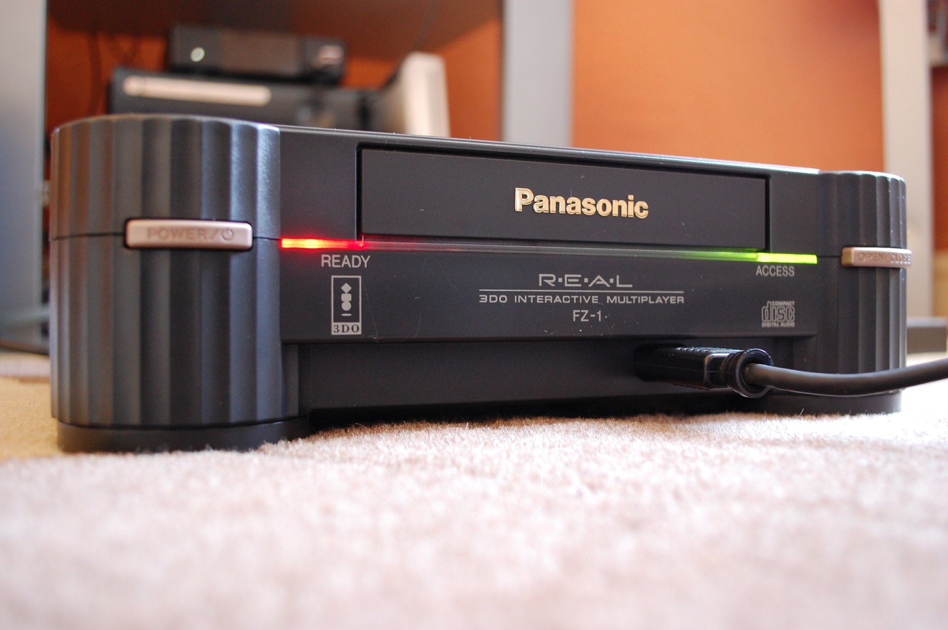
The 3DO is cool, but there’s a real missed opportunity. The LEDs don’t match the Logo, and they’re not symmetrical.
Sure, it was the ’90s and red and green were the standard, but we can do better now. Also, only the right one blinks, let’s fix that.
There, now that’s better. But how can just anyone manage this? it’s actually pretty easy. Let’s take a look at the schematic modifications I made:
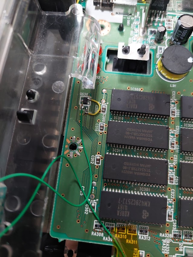
That row of LEDs is a little obnoxious, but it’s what I actually used. Let’s look at the left side first though. You can see the access LEDs are controlled by that ‘digital transistor’ which is what the electronics industry calls a transistor with built in biasing resistors. That means that when the transistor is turned on it grounds the access LEDs and they light. I don’t want that anymore, I want them to light all the time they have power. So I removed the resistor R630 and replaced it with my own, but I routed it straight to ground. This is the time I also changed the LEDs from green to yellow, and for my new LEDs I set the brightness with the new 100 ohm resistor. At this point I have 2 lights in the same places, but both on all the time. I need an activity LED again, but now it has to be blue, and in the middle.
you can see my resistor hanging off the pad that used to be for R630 and goes to the access LEDs, the other end of that resistor goes to ground on Q630 via the yellow wire.
You can probably see the problem with my ‘3 lights’ plan. The red LEDs have this nice light pipe that ducts the light from the board and to the front transparent bar under the CD drive. Those nice curved plastic features are only present on the left and right sides of that piece. That helps make sure the red and green lights have fairly distinct start and end points and don’t bleed light all over the front of the console. That also means I need a different solution.
This is my custom LED bar. I determined that each light on the 3DO was approximately one inch wide, so that means I need 1 inch of relatively even blue light. I can try to get that by diffusing it, but there’s just no depth for that. I tried a bit of white paper, but that looked obviously wrong when the console was not on. The stock 3DO gets away with 2 LEDs for 1″ of even light by having a few inches for the light to spread out. I have effectively a bunch of point sources right at the viewing area. At first I tried 10 0603 blue LEDs, each spaced 0.1″ apart on this protoboard, but that was too sparse of a pattern. I then filled in all the gaps making a total of 19 parallel LEDs (and one current limiting resistor). after much soldering I eventually got all of them connected and mostly evenly spaced. I picked a resistor that made them look alright and off we go.
All glued in, dead center
This LED arrangement is not ideal, I would almost always say that you should have one series resistor for each LED string, but in this case it wasn’t practical to hand-solder that. What I did with the one resistor and the 19 LEDs in parallel, I’m lucky it worked as well as it did. You see, each LED of the same manufacturer and type drops approximately the same voltage, but not quite. When they’re used in series, they all pass the same current, because the current in a continuous circuit is the same.
For the LEDs under ‘ready LEDs’ they’re red and are fed with 5v, since they’re red I’m gonna assume they drop approximately 1.2v. At the top if you put a meter there and checked against ground you’d see 5v, after the first LED you’d see 3.8v, and after the second you’d see 2.6v. That 2.6v is dissipated across the resistor. v=ir means 2.6v=i(100) and solving for i, i=2.6/100=26mA That means that each LED would be getting 26mA, now that’s a lot for an LED so the voltage on them is probably higher than 1.2v. To change the current though, you change the resistor. The yellow ones have the same math, but with a slightly different voltage and the transistor that switches the ground in also drops some consistent amount of voltage. If you put 2 LEDs in parallel without any resistors between them like I did for the blue ones, you can get issues because the LEDs don’t drop exactly the same voltage.
Let’s use a ‘crazy’ example, like if you stuck a blue LED in parallel with a red LED. Blue is around 3v, and red is, let’s say 1.4v (like I said, I know the ones in the 3do are somewhere above 1,2, but not much). When the voltage across the LEDs gets up to just about 1.4v the red LED starts to conduct and it will stay at around 1.4v no matter how much current you put through it. The blue LED needs 3v to light, and it will never get there because the red one is keeping it from rising. But it may have been alright if they were close enough because the voltage that is dropped across an LED is not precisely the same for every amount of current.
If you put, let’s say 1.39v across a given red LED, it might light very dimly and pass 2mA, at 1.4v it could be pretty bright at 10mA, and at 1.41v it would be passing 20mA and much above that it would burn out. But like I said each LED is slightly different so another one may have those points at 1.38, 1.39, and 1.40. If you put those in parallel and very slowly brought up the voltage then the second one would turn on first even while the first one is dark. By the time you got to 1.40v they would both be pretty bright, you may not be able to tell a difference in brightness. If the variance is too much, you have obvious dim or dark spots when the rest of the LEDs are as bright as you want them. I used all LEDs that came out of the package next to each other from the same manufacturer, made in sequential seconds so they’re as closely matched as possible.
It’s surprising how much ‘best practices’ you can get away ignoring and how much of this stuff just doesn’t really matter for one specific case of what you’re building. The moral of my story is that every string of LEDs can have as many LEDs in series as you want, but you ultimately set the current with a resistor somewhere in the string. That, and the total voltage drop of all the LEDs cannot exceed the power supplied. 19 blue LEDs in series would require a power supply around 57+ volts.
The kicad doc for this is here. I really like using kicad to sketch on top of schematic screenshots, even if I’m never going to make a board. It’s neater than paper and pencil.
This is probably the simplest mod you can do to the FZ-1 console, although it can screw up the timing of some games. I found the opening title sequence to be very out of sync with the audio on Interplay’s ‘Out Of This World‘.
The FZ-1 for Canada and Europe used the 9103 video encoder by Brooktree, yes the same Brooktree that’s responsible for the BT878 video capture IC. The datasheet for the BT856 is pretty much pin compatible (foreshadowing…) so we can reference that. It shows (like the schematic snipped above) that the video chip can select for interlaced video with pin 59. Pull that pin high and it outputs interlaced video, Low and it outputs progressive scan. Since this chip works on NTSC that means that progressive scan gives you 240 lines and interlaced gives you 480, but it sends every other line, then the next half of the frame fills in the blank lines to make a full 480. This means that this pin effectively controls either 240p or 480i. But how is it hooked up in a Canadian console? Well, the C indicates how the board is populated for those so R164 is a 4.7k resistor pulling the line up to Vaa (5v in this case) and R166 is not present. That puts us in 480i mode.
R164 is labeled 472 meaning 47*10^2, so 4.7k
There’s R164 as expected. We can see that the lower pad is connected to a big copper trace that connects to pins 58 and 57 which we can tell by the schematic are VAA, so the other side is connected to pin 59. A quick check with a multimeter verifies this and then we are free to add a single switch to control the video mode.
more foreshadowing…
I don’t like the idea of soldering a motherboard into a case so I added connectors inside. I used some 1.27mm pin header, in this case 2 pins, to create a connector so I can remove the motherboard from the case for servicing later. The cable that plugs into that is routed down next to the power button.
I found some 0.1″ SPDT slide switches that fir perfectly into the 3DO’s existing vent holes, so I carefully epoxied one in there (ignore the other one, it was later removed. Also ignore all the other stuff in this picture, it comes later in a different blog post).
That’s it, you get to switch from 480i to 240p on the fly whenever you want. The 240p picture has much more distinct scan lines because effectively every other line is black now, depending on how you’re viewing it. You can really see a difference on a CRT when looking at a grid like in the opening screen to Return Fire.
480i (I think the camera shutter may have been too fast to get it correctly, the picture seems fairly uniform)240p (very distinct scan lines)