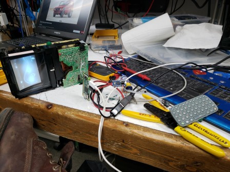
I have been working on a Pip-Boy that uses a real CRT (more to come on that later) but I decided that for input it should really have a keyboard, this is similar to the Pip-Boy 2000 Mark VI found in Fallout 76. This is a deviation from all prior designs having simple interfaces of rotary knobs and buttons (although the 1.0 prototype seemed to have a calculator-style keypad). Having a keyboard will help with the interface, meaning it doesn’t need special software to start with and can be used with a linux computer out of the box. My intent in the future is to extra inputs and outputs, but the keyboard is the first step in making it usable.

The keyboard itself is an Xbox360 chatpad. I bought this because it was cheap, and I assumed it would be a simple arduino library or python script and I’d have it working. I ended up with a little more work on my hands, but not much. Had I voiced this thought about an hour earlier I would probably have bought this, but I would have always complained that it was wireless.

I spent a fairly long time working to get this driver working. It turns out that there are apparently subtle differences between the knock-off and legit chatpads and this driver was tuned for the knock off which I didn’t have. I eventually gave up, but this would also have been a sticking point with me about the lack of portability that the solution had. Next I take a look at this arduino driver. It was promising, but ultimately flawed. Whenever I programmed it the keyboard would work, but after unplugging it and plugging it back in again (normal use case for a keyboard) it would fail, constantly, all the time. It took me a while to find the issue with this and I would also caution anyone working with an atmega32u4 to limit the amount of spam you put out the virtual serial port, it can cause programming issues with the arduino bootloader.
// Only act if a full message is available.
if (_serial->available() >= 8) {
for (int i = 0; i < 8; i++) {
_buffer[i] = _serial->read();
if (_buffer[0] != 0xA5 && _buffer[0] != 0xB4) i–; //if it gets off by one it will keep throwing out bytes until it gets to the start of another message
}
// We expect “status report” packets beginning with 0xA5, but don’t know
// what to do with them — so we silently discard them.
if (_buffer[0] == 0xA5) return;
// We *do not* expect other types of packets. If we find one, complain
// to the user.
if (_buffer[0] != 0xB4) {
Serial.print(“Unexpected packet type: “);
Serial.println(_buffer[0], HEX);
delay(100); //this makes the arduino micro programmable, fast serial communication locks it up
return;
}
if (_buffer[1] != 0xC5) {
Serial.print(“Unexpected second byte: “);
Serial.println(_buffer[1], HEX);
delay(100); //this makes the arduino micro programmable, fast serial communication locks it up
return;
}
I have added my code in red, and I will describe what exactly is happening here. This parser is written so it fires when there are enough bytes in the buffer to constitute a packet. Then it transfers the bytes out of the buffer and evaluates them. If the first byte is not one we expect, it throws out all 8 and starts again. If the second byte is not what we expect, it throws out all 8 and starts again. Think about that, if the byte you think is the start of a packet does not match the packet starting byte, why do you throw away the next 8 bytes and expect a packet to start there? This is an example of a super, SUPER optimistic bit of code. What was happening was a byte was getting dropped, probably because the chatpad booted up before the arduino and then it was forever out of sync. My fix for this was to inject a check into the loop that transfers the data out of the buffer and into the packet that’s decoded. If the header byte is not correct, I simply decrement the counter in the loop and it keeps over-writing the header until a valid one is present. This theoretically means the following checks will never fire.

With the parsing fixed I was now able to implement the character tables the way I wanted. I suppose I could have done this in the library, but I like to have a light touch on other people’s code and use it as-is as much as possible (at least where libraries are concerned maybe I have hangups about that).
if (type == Chatpad::Down) {
char a = -1;
if(mode == 0 && caps == 0) a = mode0A;
else if(mode == 0 && caps == 1) a = capsA;
else if(mode == 1) a = mode1A;
else if(mode == 2) a = mode2A;
if(a != -1) Keyboard.print(a);
This picks which array to decode the keypress to, either mode0 which is normal, mode1 which is green, mode2 which is orange, or caps lock mode. All positions that are unprintable characters in those overlays have a value of -1 so if the variable 'a' falls through this while remaining '-1' then it's either a keypress that warrants no action or something that has to be handled below.
if (code == 132 && mode == 2) mode = 0;
else if (code == 132) mode = 2;
if (code == 130 && mode == 1) mode = 0;
else if (code == 130) mode = 1;
if (code == 85) Keyboard.press(0xD8); //left
if (code == 81) Keyboard.press(0xD7); //right
if (code == 113) Keyboard.press(0xB2); //backspace
if (code == 131) Keyboard.press(0x80); //leftcontrol
if (code == 99) Keyboard.press(0xB0); //enter
if (code == 38 && mode ==2) Keyboard.press(0xDA); //up
if (code == 54 && mode ==2) Keyboard.press(0xD9); //down
if (code == 55 && mode ==2) Keyboard.press(0xD8); //left
if (code == 53 && mode ==2) Keyboard.press(0xD7); //right
if(code == 129 && caps == 1) caps = 0;
else if(code == 129) caps = 1;
The first couple lines handle setting or un-setting the green and orange lock modes, they can only be unset by pressing the same key again. The next few are special keys (not characters) and the four arrow keys are a sort of easter egg to me. I implemented the same sort of WASD-to-arrows on the Commodore 64 matrix controller and revived it here because there are no proper up and down arrows. The last two lines let you turn caps lock off in any mode and turn it on in any mode (but as you will see, in some modes it acts as shift and only in the correct mode does it act as a lock).
if (type == Chatpad::Up) {
if (code == 129 && mode != 2) caps = 0;
if (code == 85) Keyboard.release(0xD8); //left
if (code == 81) Keyboard.release(0xD7); //right
if (code == 113) Keyboard.release(0xB2); //backspace
if (code == 131) Keyboard.release(0x80); //leftcontrol
if (code == 99) Keyboard.release(0xB0); //enter
if (code == 38 && mode ==2) Keyboard.release(0xDA); //up
if (code == 54 && mode ==2) Keyboard.release(0xD9); //down
if (code == 55 && mode ==2) Keyboard.release(0xD8); //left
if (code == 53 && mode ==2) Keyboard.release(0xD7); //right
The first line does what I said above, if it is not in orange mode then when you release shift it does not lock, if in orange mode it locks. The rest just release the special keys they pressed. The entire rest of the code is just housekeeping on the LED outputs for the mode indication, I could have used other I/O for encoders or buttons but right now I wanted to keep it simple. There were other things I could have done, including reprogramming the PIC (but seriously, fuck PICs) or just using another library, but this is the solution I ended on.
My code is here and my repaired driver is here.