Archive for November, 2019

Reverse engineering a Shop Bot ROM

November 13, 2019

After dumping the ROM from the shop bot we were intrigued by what we found.  Some of the strings in the ROM indicated that there was a basic interpreter on there, and there was even plaintext BASIC.  After some digging this is what we found.

20191108_162106

Blue Earth Research was a company that made microprocessor development boards, presumably for industrial use.  They packaged (in our case) an 80c32 processor, a ROM chip, and I/O expander, and made it all as compact as possible.  They also did work with the 8052 and other processors in that line.  Among the series of boards they offered was the Xplor 32d, the ‘d’ standing for digital as there were boards with on board analog to digital converters.  They provided the BASIC interpreter’s hex file, the assembly source for a program that could load that hex file onto the microprocessor, and the source for libraries for use with peripherals such as a keypad, an HD44780 LCD screen, and X-10 automation hardware.  There were also example BASIC programs that showed some of their BASIC’s more unique features.  There was also a C compiler for this architecture, but since that doesn’t have anything to do with our ROM dump we’ll skip that.

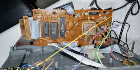
Before even starting in on the code we traced the whole board to determine which pins were where as far as I/O and how the chips were wired up to determine the memory map.  This information is all in one spreadsheet contained in multiple tabs, the memory map was eventually expanded to contain details of the code we disassembled.

basic-program

To help with this we employed the disassembler dasmx.  This is extremely easy to use, and even though it is not open source it is free to use.  This program is fairly smart, but it’s not magic.  It will interpret all the memory as code memory unless told otherwise and because there are no distinctions calling out the beginning of data it tries to decode plaintext as code.  We originally were concerned that the ROM dump was incomplete because a hole in the BASIC exists between 0x10C1 and 0x13FF.  Upon closer inspection the code after 0x13FF references line numbers that should be in the top code snippet and are not present, implying that it is not from the same program.  In addition to that, one of the new BASIC commands is CALL which jumps to a memory location and starts executing the assembly there, and the BASIC snippet starting at 0x1000 ends with CALL 7000.  Interestingly, that command is referenced in the source files of the example programs explaining how to use this development board, so that confirms our suspicions.

console-similarities


Part of the instructions for how to use this dev board include assembly libraries that can be called from BASIC that use the peripherals.  Things like the LCD, keypad, and X-10 integration were provided by Blue Earth Research and instructions were given for them to be loaded at 0x1E00.  Our ROM includes these exactly, and by adding the line labels to the symbol file they disassemble and are readable (even if I don’t think the main shop bot program is using them).  It’s a bummer that the source for Xplor Tiny BASIC is not provided, but it helps that the same person wrote that as wrote the loader for it.  RELOAD.A51 contains some routines that are almost, but not exactly like routines in BASIC.  Specifically the string printing and console output routines.  The differences seem to come from the fact that BASIC has built in support for the LCD and therefore has to check if it should print there or to the console.

port-writes

The other source files also helped determine how our program was interfacing to the 82c55.  The wiring only decodes some of the address lines so it would be possible to write to the peripheral chip with a number of memory locations, but the source files clearly show constants of 0x2000 for port A, 0x2100 for port B, 0x2200 for port C, and 0x2300 for the control registers.  This is in the disassembly as well, but the assembler eliminated the constants and now references to these numbers are sprinkled throughout the code.  This helps determine what is going on with certain sections of code and labeling has progressed based on this.  As a note, some of the labels in the source code we have are not present in the disassembled code.  This is because if nothing calls that memory location then the disassembler doesn’t know it is supposed to be logically distinct and there is no placeholder label generated.

keyword

This BASIC is interesting in that the coding convention calls subroutines and then immediately after the call is the data to be used in that subroutine.  This means that the subroutine can get the data by looking where the program would jump back to and pulling information from there until it hits the end.  One example of this is the keyword subroutine.  When reading the BASIC program the interperter needs to know if it’s reading a valid command, and if it is then it needs to execute that command.  Our code contains a call to the keyword routine and then immediately after is the basic command in plaintext, except the last character has the most significant bit set.  This is so the routine knows when to stop reading data (there’s code after that).  There are no null terminated strings here, just checking to see if the byte is greater than 0x80, if it is 0x80 is subtracted and that is the last character in the keyword.  This convention is also used when printing strings to the console or the LCD.

setup

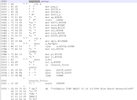
Doesn’t this look a lot like the init section of an arduino program, complete with the serial print of what it is and that it’s booting

The remaining parts of the disassembly were made by recognizing when special registers were being used.  Things like transferring data to or from the serial buffer are fairly obvious (either moving things in or out of the sbuf register).  Setting up interrupts and timers, as well as setting the direction of ports can all be gleaned without looking closely enough to see which bits are being set, just that those registers are all being written with values in succession near the beginning of the program.

This is where we are right now with the disassembly, it’s been interesting and we might dig further into this at a later date, but for now our curiosity has been satisfied.  All the files we used for this are up on github, that includes the last version of the disassembler, the rom dump, the latest revision of symbol file for it, and the listing that it decodes.  The board wiring and memory map are also there.  The source files from Blue Earth Research are also there although they are also in the internet archive.

Dumping the x88c64 multiplexed rom

November 12, 2019

20190801_192356

The 8051 is in everything.  I’ve won pitchers of alcohol by betting that a given device contained an 8051.  It’s in USB hubs, bluetooth microprocessors, UPSes, and even SOIC16 packages and smaller.   That’s not to say it’s a sane architecture, but it’s ubiquitous.  The problem I have is pin multiplexing.  The 8051 has internal rom, that’s all fine if you’re only using that internal space but the 8031 is the rom-less version.  The 8031 has all of it’s program memory offboard which is very nice for the purpose of accessing it to dump the data for analysis and modification, except in this case.  To save pins on the 8051 series the data pins are multiplexed with the lower 8 bits of the address bus.  In most circuits that just means that a latch is used and the processor interfaces with a standard parallel rom.  This architecture became so ubiquitous though, that special multiplexed roms were created to deal with this exact scheme and allow for smaller boards and less circuit design work.  The x88c64 is one of those chips.

20191107_122342

The Arduino Mega is a very nice tool for twiddling bits, it’s 5v logic, got lots of I/O and the only connector on it you will likely need is a 2×16 0.1″ pitch male header.  The arduino platform had always annoyed me with its non-grid pin spacing so shields have to be custom laid out rather than just using protoboard and only populating some of the grid.  The mega avoids that in part by the new big connector being a monolithic 36 pin header.  5v and ground are available on the top and bottom two pins and the remaining 32 pins are I/O.  All of ports A, C, and L as well as hardware SPI pins are available in those 32 pins, even though I usually abstract that out and ignore the underlying hardware ports in my code.

20191107_122349

One useful thing about this rom is that in addition to there basically being a write protect pin, the write cycle needs three whole writes of specific data basically saying ‘are you sure’ and if all that goes correctly then on the fourth write you can change the data in the rom.  This is one way to do away with funky programming voltages and still have some form of protection so you (I) don’t accidentally blow away the rom you’re (I’m) trying to archive.

x88c64-write-cycle

The code to dump this rom is abstracted out and will run on the atmega2560 under the arduino ide, the board made is for the arduino mega although I know you could use any atmega2560 breakout to read one of these roms with this code.  I didn’t write the code to dump this one, Frank did.  I tried and was stymied probably by jumper wires with no continutiy.  We sorted that out by soldering up an adapter instead. Let this be a lesson to you: never breadboard where you can solder, you’ll spend more time debugging it than making it.  The code is fairly straightforward, but as it’s probably just the first in a series of custom rom dumpers a couple routines were abstracted out.

void WriteAll(int pinstart, int numpins, int incdec, int value) takes the first pin of a set of pins you want to change, how many pins you want to change, whether you’re counting up or down, and a value you want to write to those pins.  That value is not just binary, this function takes an int and strips it down bit by bit setting pins in a series.  This is limited to adjacent arduino pins because of how the counting works, but is still incredibly useful.

int ReadAll(int pinstart, int numpins, int incdec) does the same thing as writing out, except it returns the value put together from reading individual bits.  These functions can be turned into specific functions per program by simply using one #define statement for each new function you want to create.  #define WRITE_AD(value) WriteAll(22,8,1,value) writes the value passed to it starting at pin 22 and counting up for 8 bits of data.  #define WRITE_A(value) WriteAll(37,5,-1,value) writes the value passed to it starting at pin 37 and counting down for 5 bits of data.  #define READ_D(value) ReadAll(22,8,1) reads 8 bits of data starting at pin 22 and counting up.

The remainder of the code is a straightforward interpretation of the timing diagram in the datasheet, hopefully this will help anyone who needs to dump this oddball eeprom.


Vtech Pre Computer Power Pad upgrades

November 5, 2019

20191104_194438

All inspiration for this came from a recent hackaday post.  It is a bit fragmented so let me try to bring the information sources together as well as add my own.

Hackaday post

Hackaday.io project (linked from above)

Thingiverse (contains best image of pcb traces)

Original creator’s personal blog

z88dk thread

Additional information on a similar computer

There is much more information out there that needs to be compiled as well.

Now, as for my contribution.

y6hllrs

I want to eventually use this as a CollapseOS machine, I think it’s in the spirit of that operating system to be built out of salvage components, but this right here seems to be a ready made machine for the job.  After Makerfaire Detroit Frank and I got an s100 bus system consisting of two poly88 chassis, an ithica audio z80, a percom monitor rom, a solid state music io-4, an sd systems expandoram, and a zrt-80 terminal.  We got the various cards fixed and Frank modified the monitor and streamed basic over to it over a serial port to run from RAM.  It’s a pretty capable system and I already have four more cards for it and one more in the mail (none of these were really needed, but whatever).  That is the main workhorse z80 system and has been extremely useful for learning how the whole architecture works as well as learning some tricks from back in the day.  We will probably end up running CollapseOS on there some day, and probably a version of CP/M if we ever get disk controller cards.  Using that knowledge I’m going to try to make the Pre Computer Power Pad a useful z80 laptop.

Rom Dumping

The first thing to do after learning about all the work already done in MAME was to dump this rom and see if it was already emulated.  After looking at this nice annotated layout it seems that the mask rom used in these computers is pin compatible with the 27c2001 2 megabit rom, and an eeprom programmer will dump it as if it were one.  It turns out we are the first ones to dump the rom contents of this computer (27-5373-04) and put it on the internet.  With some minor patching it runs in the pc2000 mame driver as a gl4000 (just swapped the rom and recompiled).  This is incredibly powerful and lets us interrogate the code as it runs, setting watchpoints and single stepping as we see it handling functions like printing (we’ll get to that).  This rom should be up on the MAME guys repository soon and the new addition to the mame driver shortly after.  There’s still work to be done to add the printer port to the driver for computers that come with one, but we haven’t got that done yet.

Printer Port addition

20191104_195044

Now, I don’t say parallel port because this port really is only equipped to print.  I started from here with the helpful information on the missing components.  From there I determined what jumper wires were needed by analyzing the circuit and links to nearby chips.  This was complicated somewhat as it seems that under battery power some circuit generates a negative voltage and that is what the rf ground is running at? I don’t know the power situation with this board but I don’t really like it.

20191104_194535

The original transistors of Q10 and Q11 were LM9014C and LM9015C respectively and I replaced them with a PN101 and a PN2907, which roughly work out to a 2n3904 and 2n3906.  The PNP transistor serves to pull down the strobe pin as a noninverting output (10k pull up) and the NPN transistor acts as an inverting input from the printer’s /BUSY line.  This plus all the resistors that are missing being 10k and the fairly obvious 74ls244 (obvious because of the wacky pinout) gives you a working printer port circuit.

20191104_194541

This won’t let you print, but you have an electrically functional port.  The english rom has the commands LPRINT and LLIST missing from the BASIC keyword table so you can’t exercise the port, but flashing the german rom to a W49F002 (thank you salvage BIOS roms) and it prints just fine.  Work is progressing to add those commands back to the english rom, it’s just not done yet.

20191107_122741

One final word on the printer port, and speculation on why it was not on the US version of the laptop.  The ‘244 is hardwired to be on all the time, at least that’s what it looks like to me.  The data lines for the printer port are shared with the key matrix, and from what I can see the key matrix scanning signal is being broadcast out all the printer port data lines at all times.  The printer doesn’t respond because the strobe line isn’t used, but the data’s there.  This reminds me of Bill Herd’s story of the commodore that had full system bus speed scanning the keyboard matrix with no buffer and it would crash if you got it near a TV.  The FCC may have had the final say about this design.

NiMH charging addition

20191104_195036

The last one was really puzzling out exactly what to do based on information from the last guy.  This is a new contribution.  I decided that since this was a laptop that it should behave like one.  To me that means a rechargeable battery with charging circuit inside.  This comes partly out of all AA batteries in my house being Enloop NiMHs and my desire to not take them out all the time to charge.  I also wanted to keep the original functionality of being able to use non rechargeable batteries for emergencies or just situations where you can’t get rechargeable or you lose one.

20191104_195026

I implemented this with a switch on the back to switch between R(echargeable) and A(lkeline) batteries.  What that does is when the switch is in the A(lkeline) position and you are running off batteries the battery ground is run to the pass-through pin of the barrel jack and thus connected to the system ground.  The positive is connected to the ~5v input to the pcb.  When you are using the barrel input the pass-through is disconnected and the batteries are out of the circuit (on the ground side).  The input to the barrel jack goes through a dc-dc converter and also goes to the ~5v input on the PCB.  This is different from stock in that the barrel jack used to feed a different part of the pcb with ~9v but it would have complicated my circuit to do that so I regulated it down to simulate the battery voltage.  This means the allowable input voltage is now a much wider range, instead of being just 9v you can feed it 7-20v and it would survive just fine.  I had to swap the barrel to one that would accept standard 12v supplies, the original one had a center pin that was too big.

20191104_195024

In the R(echargeable) position the pass-through and system ground are connected together.  Also the barrel jack moves from supplying the pcb through a dc-dc converter to running a NiMH charger to charge the batteries.  This means that in R(echargeable) mode the batteries are always powering the laptop, just sometimes the charger for them is being powered too.  The charger’s LED was relocated to the front lip of the laptop to indicate charging status.

20191104_194503

These modifications allow the laptop to be run off a wider range of voltages, charge its own batteries, and in a pinch you can swap out the batteries if you need to.  Truly a versatile configuration in preparing for the collapse.

20191103_164405


ToDo:

test and install supercap and diode circuit to keep internal sram alive when AA batteries are removed

maybe patch internal chip select lines to unused cartridge pins for remapping without opening the case (would then need jumper cart)

bigger screen? looks like the hd44780 lines just go from the main board to the top of the laptop

patch english rom to allow LPRINT and LLIST

patch all roms to restore peek and poke (list of commands seems based on microsoft basic for the z80)

fix mame driver printer routines/clock frequency

upload dumped power pad rom to mame

port CollapseOS