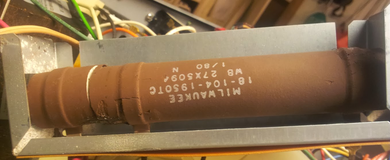
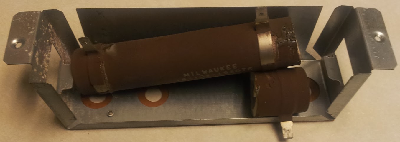
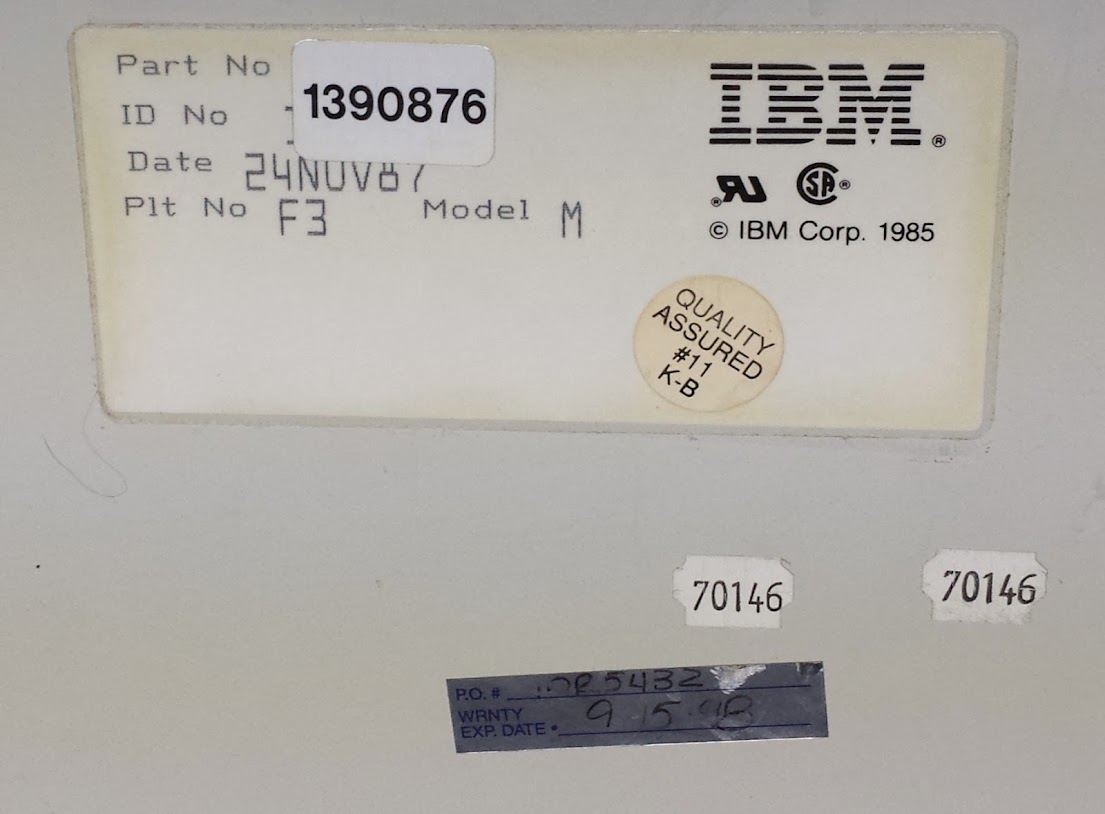
I was at an electronics thrift store recently (I’m not advertising here partially because I don’t care that much, partially because there’s another one still there and I may go back for it). to get something, but while I was wandering around this caught my eye. I originally called it an “IBM Model F” but that’s wrong, it’s a Model M, but it has 122 keys. It does self identify as a “Plt No F3” but that may be a coincidence. What I can tell you is that it’s a part number 1390876, was made in 1987, and someone warrantied it until 1998 (maybe?).
How’s that saying go? “This is my keyboard, there are many like it, but this one is mine”. Well, in this case there are none like it… anymore. I decided that there were some aspects of a bunch of different keyboards I wanted to incorporate into the layout of this one. I started by deciding what I wanted in my keyboard. First I wanted to make sure all the keys had a useful function. Second I wanted to use as many keycaps from the original layout as possible. Third I wanted to have numlock on at all times (or rather never have the keypad do anything but numbers and math symbols). Next I needed to put back a windows key on a keyboard distinctly lacking one. The arrow keys had to be restored to a sane configuration. Finally I wanted to have commonly used key combinations assigned to single keys.
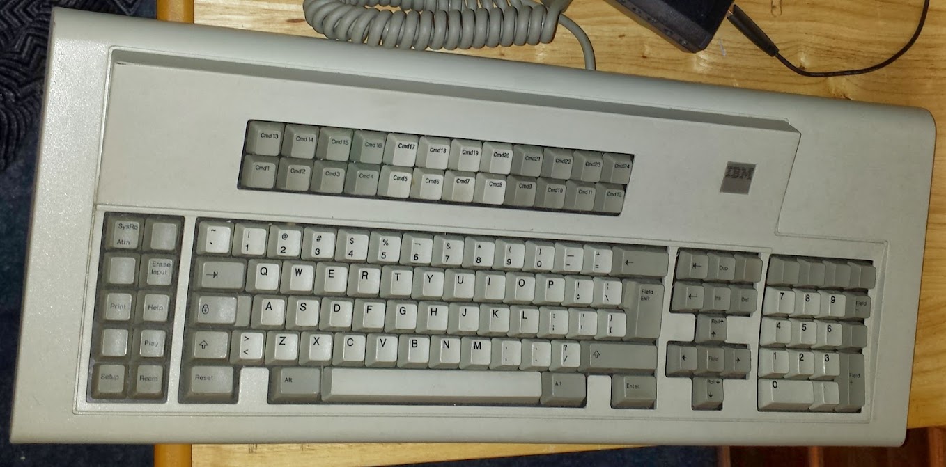
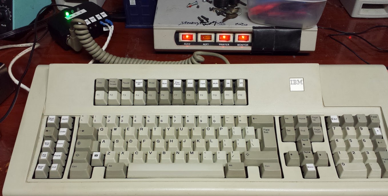
The keyboard as it originally looked
I really liked some of the historical things this keyboard brought to my attention. There are a bunch of symbols that are present on it that I’ve never seen before. The number one has a shift function of a pipe rather than an exclamation point. The problem is that the pipe key looks the same as it does on more modern keyboards. That’s actually a broken pipe symbol which used to be a different character (but for some reason the broken pipe symbol remained on the keyboard while the use moved to the pipe). The alternate function of the six key was a bar with a hook on the end which I have been told used to represent a logical “not” state. I’m pretty sure I can’t pass that as a HID keycode and have any modern operating system handle it. The exclamation point is occupying a key with the “cent” symbol, which falls into that category of ‘symbols we don’t really use in modern computing’. I liked how the numpad didn’t have numlock functions defined on it, but unfortunately the plus sign is occupying the spot the enter key does (and I use that one a lot). I do have another key to play with however as there are two normal sized keys above it rather than the large key that’s usually there (and I put the small return key on one of them, and a carrot on the other). The number of keys that IBM didn’t even bother to define I found interesting. The function keys are plentiful, but I wanted them to be ‘f’ keys, so I switched those. The pointed brackets (or greater-than/less-than symbols to some of you) were on the same key, I thought that was interesting, but I decided to mostly put it back to qwerty in the major ways. I kept the funky enter key (‘field exit’ it says) and that moved the pipe key down. The left shift key is smaller on this keyboard, I chose to put the windows key there. The arrow keys got moved to it’s proper configuration and I put a context menu key below it (what else would I do there? The left ‘alternate f keys’ I decided to take direction from the sun keyboards and map things like copy, cut, and paste there. I also added some others I found useful in web browsing (the ‘untab’ key as I call it was present on the keyboard, but in the cluster above the arrow keys) and one that my Lenovo T60 taught me about (next web page). The top row of the f-keys I went with media keys, a print key that was on the keyboard originally, the scroll lock cluster (which isn’t on this keyboard anyway, and I didn’t need scroll lock) and the escape key.
Sorry about that, there’s no real logical place to break that block of text up that wouldn’t just be arbitrary. I liked that some of the keys had symbols and no text as opposed to modern ones (backspace, tab, caps lock, shift, untab, return) and some had less than entire words (del, ins). The controller is the brainchild of a fantastic guy on the geekhack forum by the handle of Soarer. I found out by reading the entire forum thread here that the code (or maybe documentation) wasn’t released for so long that someone else developed an alternative that now has other and different compatibilities (which is kinda cool).
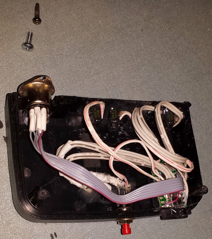
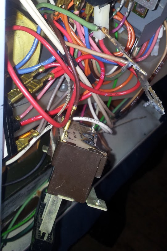
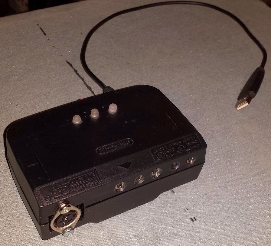
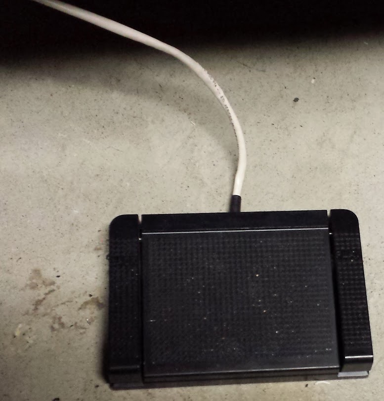
The hardware is trivial, it’s just a Teensy 2.0, a keyboard connector and nothing else. The teensy is really great for being stupidly cheap and able to act as a USB HID device. The teensy 3.0/3.1 is out, but that’s a full 32bit arm processor and so many levels of overkill that I couldn’t bring myself to consider it for this project. I chose to add the three indicator LEDs because this keyboard doesn’t have them. I also chose to add the reset button in case I wanted to put on a new teensy firmware and didn’t want to open the case. The last feature I added was that I broke out all the aux inputs as 1/8″ headphone jacks. I did it wrong. I shorted the ring and tip together and connected them to the aux input and the shell to ground. I should have connected the shell to ground and the tip to signal. I now have to use stereo male phono connectors because mono ones short it out and have the key constantly pressed. I really like the aux inputs for things like footswitches, I mapped them to left and right, (for surfing image galleries) space for a pause key, (watch this space for a laser line break switch using a comparator) and page up and down for surfing blogs. The footswitches I had were normally open and normally closed. Opening it up, bending the leaf switches apart, and flipping the switch over was all it took to make it normally open and work with the controller.
In the end I decided to label the keys with my dymo letratag (free after rebate from black friday a long time ago) and I have transparent keycaps on order to make them all the same height (and protect the labels). I’m also looking into having key caps printed up, but it may not be possible (the company says they do it but some people say they’re unresponsive). The firmware for the keyboard is seperate from the re-mapping and macros. The config file is compiled into a binary form and uploaded to the microcontroller. The code allows for all sorts of cool features and the documentation tells all about it, but I’ll mention a few things here. You can make macros without using any modifier keys (alt, ctrl, shift). You may also want to use a more conventional ‘MAKE’ ‘BREAK’ keypresses rather than the ‘PUSH’ ‘POP’ that are supposed to restore the keypresses to the original state. I had problems using my ‘shift-tab’ key with the ctrl key to make ctrl-shift-tab so I chucked all of the ones I wanted to use in combination (and my config file reflects that). I also had a problem with the PAD_ASTERISK keywhere I remapped things in the wrong order, causing two keys to be the ‘carrot’ key (the fix was to make the PAD_ASTERISK a macro from it’s original key rather than a remap. I think that’s all the oddities I found, but I didn’t even try to use the layers function or some of the other stuff.
The world’s most obnoxious keyboard now has USB!
Continuing adventures!