Archive for June, 2014

Further unearthing of the Hit-Clips technology

June 15, 2014

A few months ago I was reading hackaday, like we all do when I ran across a curious article.  The article was this one from ch00ftech on reverse engineering the Hit-Clips trendy portable audio technology.  I found this odd for several reasons, but mostly because I just assumed everyone knew how they worked.  The reasoning for this assumption comes from having torn one apart as a kid, deemed it trivially simple, and gotten bored with it in minutes.  I remember quite vividly one christmas (or was it a birthday) when my sister got one as a present and condescendingly sneered that it’s useless ‘without a player’.  Oh how wrong she was.


It’s true that you can’t really do anything with just the flash chip sitting there in the palm of your hand, but the player is one of the simplest devices possible.  It consists of a speaker, a battery, and a button.  All the smarts are located in the chip, the ‘player’ is just a breakout for the chip.  I, however have a slightly more interesting piece of retro technology to dissect: a record-able Hit-Clip.

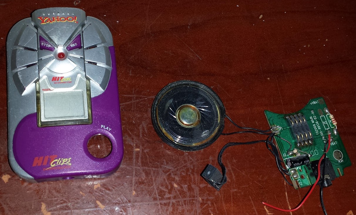
The first thing I would notice is the bright and shiny “Yahoo” logo, this being from the year 2000 those of you that remember the dark times before lord and savior google led us to the light will feel either a wave of nostalgia, or nausea.  This device was marketed so that you could record your own sound clips of uselessly short duration and play them back at your leisure.  Taking a look at the circuit board one might notice that there is no brain in this player/recorder.  There’s hardly any components really, let’s take a closer look.


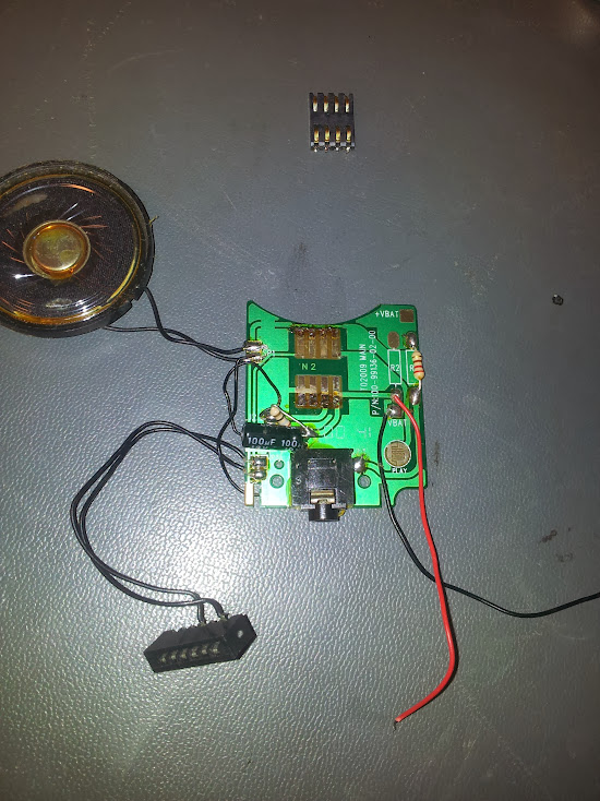
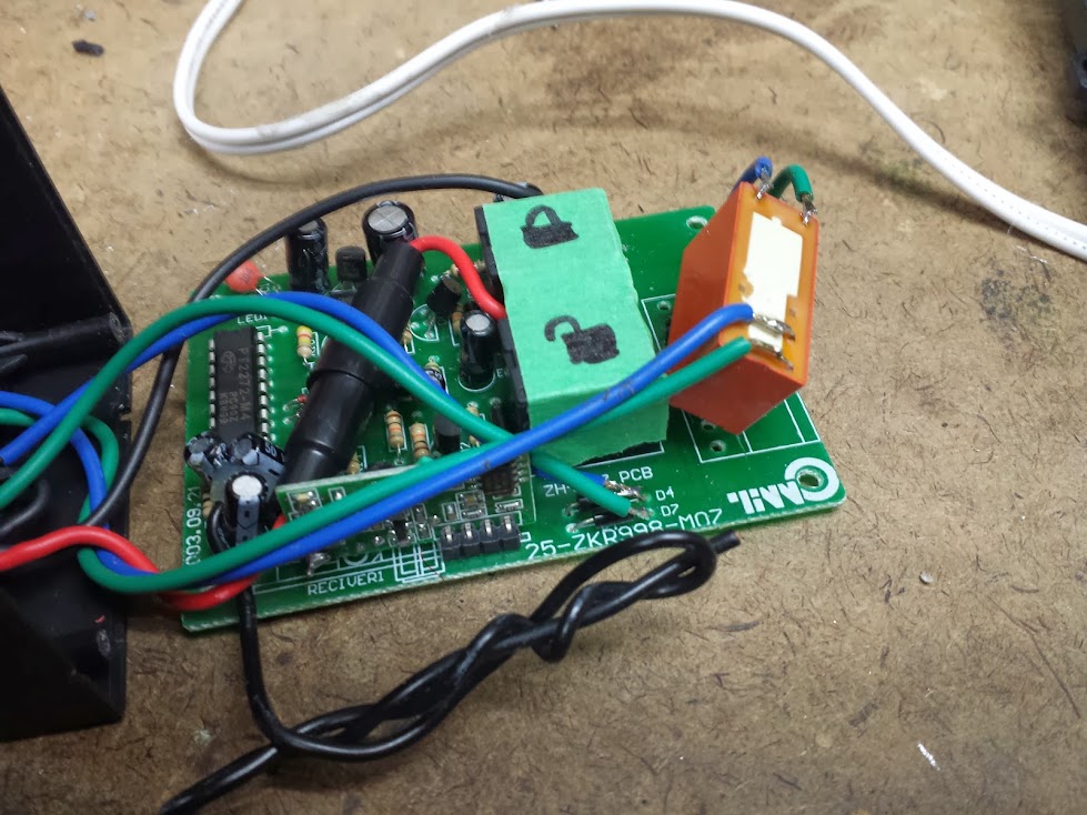
There we have a speaker, headphone jack, two resistors, a capacitor, battery connections, and a card edge connector.  The card edge connector has six pins, but only two of them are connected to anything.  That connector is the part that makes this particular player unique, that’s the audio input.  There’s no fancy serial connection like the computer connected barbie of the same era, those connections are good old-fashioned analog audio.  Presumably they didn’t use another headphone jack because the demographic for this product could not be expected to read and understand labels like ‘input’ or ‘output’.  I remember (and some checking around will yield the manual) that there is a cradle that this connects to for recording.  The battery connection is pretty obvious (and labeled) so I quickly reversed the schematic and came up with this:

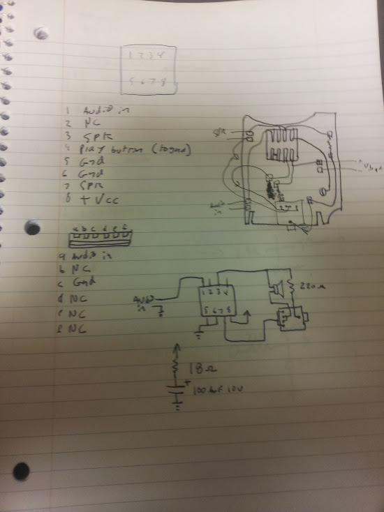
pin labeling is correct, but the schematic omits the play button


I find it nice that they actually used the switched headphone jack on the bottom correctly so as to mute the speaker when headphones are plugged in.  The low-pass filter that was talked about in the more thorough article linked above is simply the mechanics of the speaker, or, on the case of headphones, an in-line resistor.  I would have figured the resistor and capacitor wired together would have been in the audio circuit, but they were just on the power lines as a filter.  The interesting part about this device is the recording functionality, and while I have pictures of the board inside the module I didn’t reverse the schematic, mostly because I am not going to un-pot the chips anyway so it doesn’t interest me enough to do so.  Here it is, the Hit-Clip recorder revealed:


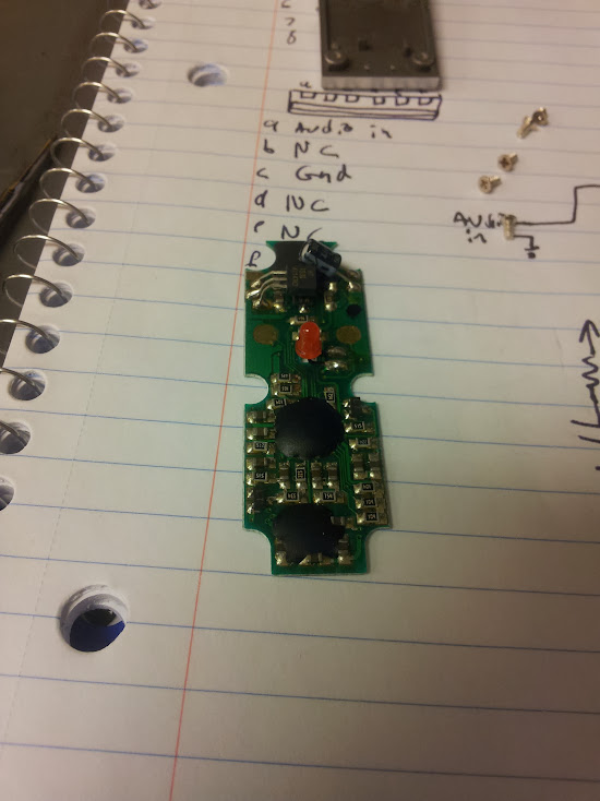
Just because I don’t feel like tracing out that circuit doesn’t mean I’m not interested in seeing it done.  I will drop this in a flat rate envelope to anyone who convinces me they are going to reverse engineer it and do a write-up because it would be nice to get that information out there.

Reverse Engineered Bubble Display

June 15, 2014

I was at hamvention a few weeks ago and ran across some digital stopwatches, the salesman made me an offer I couldn’t refuse so I got all four.  Each had a bubble display inside, but not in a terribly useful configuration.  The displays have nine plastic lenses, but only numbers two, three, four, five, seven, and eight are populated.  that’s a froup of four, a space, then another group of two.  I should also mention that I don’t actually need any more displays, but they always seem so useful that I can’t help myself.  I wrote a generic matrix driver and threw it up on my github here (I swear I’ve written this code a million times, so here it is for general use). The number on the back says “LTB-1467S” T8416 Made in Taiwan, so if anyone else needs this pinout hopefully google will lead them here.

Central locking system conversion to remote power switch (intro to the bistable relay)

June 14, 2014

I a continued effort to re-purpose un-needed items into generic solutions to common problems I have converted this no-name-brand aftermarket central locking system into a remotely switchable power strip.  The system was given to me since the only part of it that was needed for a friend’s hack was the solenoid actuators, with only the transmitter/receiver pair left I thought this would make it at least somewhat useful.

a most generic box


how it originally looked


So, this system used one solenoid and applied voltage one way to lock and another way to unlock.  There are two remotes and the receiver module has spots to wire up buttons for lock and unlock.  The first thing I did was pin it out, the lock and unlock signals are labeled in the above picture.


The inside of it wasn’t too hard to figure out.  Power and found were red and black, 12 volts DC since it was meant for (modern) automotive use.  Brown and white were wired to themselves on the board which left the question as to which was control and which was output.  I checked the bottom of the board and verified with a meter that when actuated to lock blue and green source and sink 12 volts momentarily, and unlock flips the polarity.  Now, the question is how to latch the output so one button closes the circuit and another opens it.

One solution would be to use a flip-flop and set, or reset it depending on the signal.  It might even be beneficial to trace back before the relays to the logic level signals and use those directly.  Then you could simply use the output of the flip-flop to run a fet, SSR, or relay to control your device, but I think I have found not only a simpler solution, but a more efficient one.  You may not think that more relays would make the system any better, but there’s one type that they don’t usually talk about that solves this problem perfectly.

When I was thinking about home automation I wanted to use electronics to flip lights and fans on and off to conserve power, but I had a problem: if I use a relay then it’s always burning power in one of the two positions.  If I hook up a computer in addition to the conventional light switch then either you can turn out the lights, or my sensors or timers can, but then the efficiency gets eaten into by the relay coil burning away the watts silently heating the wall.  I theorized that you could make a relay that is stable in two positions, one that has springs that hold it closed, but coils that pull it to one relaxed state or another.  This would be rather fiddly to build, but it’s not a complex idea.  Another design could use a ratchet to increment along a series of contacts making a kind of electro-mechanical rotary switch.  I really didn’t want to build either of these, but I couldn’t believe they were new ideas.  A trip to google later and I got the term ‘latching relay’ or ‘bistable relay‘ and a couple weeks later ebay delivered me a few to play with.  As an aside, the other design (the multi-pole one) is called a stepping relay.


There are multiple types of latching relay, I chose the type with one coil and flipping the polarity would change the state of the relay (since that’s what the system I had did).  In reality I could have treated both signals individually and used a common ground, but I had this available to me so I used it closer to how it was originally designed.  Now I have a single pole single throw relay contact as an output of an rf remote.  I packaged it all up and the result was this nice neat box.


Now I still didn’t have a use for it in this state, so I threw it in a box, connected it to mains, and have a wireless remote power strip.  I may not have much of a use for that either, but now I can just plug it in and go.