So, as the story usually goes: I bought the crippled cheaper version and dropped way too much time upgrading it. This time it’s the tl866cs EEPROM programmer. but this thing is much more than that, it does reading and writing of EEPROMs, sure, but it also does avr, pic, 8051, PLDs, all sorts of stuff. The part that sold it for me was that… well, what do you think this programmer is? it’s a micro with IO expanders (or at least buffers), and digitally configurable voltage regulators. so, crap-tons of IO, definable power and ground pins… this thing can test piles of logic chips! all you have to do is apply input signals, take output signals, check against a known good and report faults. So it also tests 7400, 4000, and even ram chips. So this thing is an absolute godsend, it has tons of chips in the database, hex editor built in, configurable pretty much anything.
Now, on to the differences in the versions. I bought the tl866cs variant which has the 40pin zif socket, but no ICSP connector. Don’t get me wrong, it has the cutout, has all needed passives, just needs the header. The full version is the tl866a, what I wanted to upgrade to. Now, as far as I can tell this is an original Chinese design: I don’t know of another programmer in a similar form factor, they have their own GUI (unlike the Saleae I modded the other day). They are understandably hesitant to release any schematics, firmware, or even what chip is driving the entire thing.
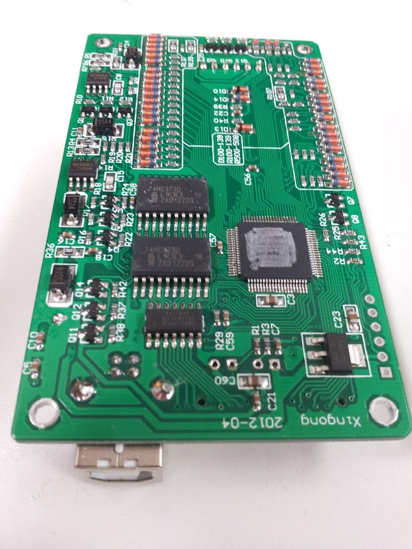
Let’s start with the chip. They have scraped the part number off of the package (rotary tool of some kind) and apparently thought this was enough. I won’t even go into the brute force method which starts with the USB Vid is licensed to microchip if I’m not mistaken and they have this wonderful thing these days where you can sort by package to get all possible PICs in that package, then trace power, ground, ICSP, and crystal and you have the family, if not the exact chip (oops, I guess I got into it). The really hard way involves acid and building a complete picture of all it’s specs based on the silicon die, but we’ll save that for military ASICs (You can’t hide from us!). The easy way is to ask around other people who bought it (they are probably electrical engineers/hobbyists, who else buys no-name Chinese stuff like this) and find someone who can read the slightly less worn away chip they got in theirs. Now we have the one unknown part we can proceed to reverse engineer a schematic pretty easily. I know it’s time consuming, but luckily we can outsource that job to people on the internet with more free time than us.
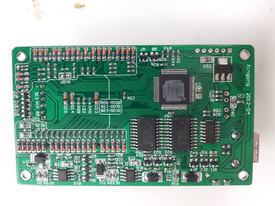
bottom featuring shaved IC and it’s ICSP header… facepalm
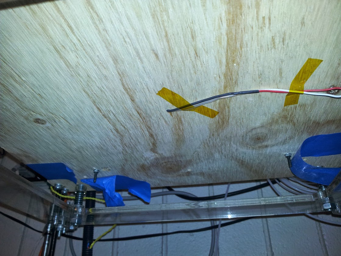
Just a side note on the construction: this board is designed fairly well, I only have a few gripes. It seems fairly obvious that these PCBs are machine assembled and the final product is hand assembled. They use standard 0.1″ pin headers to connect the boards and solder wires to hold them in place. My main gripe is not the wires, they’re redundant grounds, my gripe is those darn LEDs, they are on long leads that go all the way through the boards and solder in the bottom. You’re already putting in all those pin headers, you can’t put in 4 more pins!?
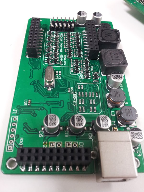
modular pin headers… thank god
Ok, now that we have the hardware, let’s move on to the software. This is where I got hung up, bored, and let someone else do it. We’ll start with my attempt. First thoughts: different USB Pid for each model (so very wrong). we’ll skip my pawing at the minipro files looking for plaintext and move right on to the fact that someone actually discovered that there is a bootloader that takes firmware updates, the firmwares are encrypted, and the bootloader checks them on boot to see if they match. They also decrypted them, reverse engineered the bootloader, created an application to generate bootloader and whole firmware unencrypted hex files with user settable IDs…. duuuuuude, so much work, such nice documentation.

my original serial and dev codes
Now, looking into the future, there is also talk about creating custom chip libraries and chip testing/programming algorithms…. I envision a utopia future where there is a crowdsourced effort adding chips to the library, maybe even designing better hardware (using digital pots to get finer power control than 8 distinct voltages). but I digress…
boost converters on the left
OK, now I have a firmware image to write to the PIC, all I need to do is whip out the pickit3. Oh, I don’t have one. pickit2? Nope, hmm, I have something for PICs around here… AH! here, a microchip mplab ICD 2. Ok, no problem install mplab, and visual studio? I don’t care, whatever, just install it. OK, now how do I set it up? uh, ok, select programmer, blah, blah, error… huh? Well the programmer failed the self test, but nothing’s plugged in to it and it says it passed the test in the settings menu. Uh, we’ll just ignore that. now connect it, import the hex, set the config bits from the hex, aaaaand crap. it can’t recognize the PIC. I don’t know why, the voltages are all fine, it says it’s supported, please work? No, ok, well screw you too mplab. how about some 3rd party pic programming tools. None support this hockey puck of doom. Ok, fine, just use the easy serial programmer. It’s only like five components and I’m in a well stocked lab and…..you want WHAT now?! an 8.2v zener? no I don’t stock those. hmmm, how does this even work… OH GOD, uh, we’ll just forget how they’re doing that voltage regulation… and floating grounds… ok, here’s a more sane one, still needs a 12v zener, that’s ok, I actually have those. Get it all breadboarded up and find out that my 3rd party client supports the PIC18f87j50… with only one of the many compatible programmers he listed. Fine, what else? ok, here, a parallel port programmer, it doesn’t get any more simple. so I need a 74<cough><cough>05, yeah, I’ve got one somewhere, I’m sure it’ll work just fine. Oh, hmmm, it says I need a Vpp of no more than 3.6v, and I think I need logic levels to match. fine, I’ll just lower the voltage on this buffer chip…. crap. it doesn’t go low enough. This is the point where I considered breaking out the textbooks to build level shifters out of BJTs to get the right voltages (I would have already built a pickit2 clone as they can be programmed with the serial thing, if I had the right model PIC for the brain). I just know these chips will work out of spec, what is it Scotty said? “A good engineer is always a wee bit conservative… at least on paper”. Ok, let’s do it. Doesn’t detect programmer… crap. well, it’s breadboarded up, I’ll just… oh… that’s how it checks for this simple programmer, it uses a free input pin to sense the inverse of one of it’s own signals and twiddles it to be sure that, yes, it really is seeing it’s own tail wag. and the pin fell out. Ok, back in, click button, YAY! the programmer is recognized. ok, connect the PIC… one of the pins isn’t used… the one with the bjt… nope, I don’t care anymore, leave it off, keep on trucking. Dump the chip. well, it’s not throwing an error, and it seems to have autodetected the PIC. (yes, hooking up a programmer is exactly all it takes to bypass the ‘scratching off the number’ routine since they LEFT AN ICSP HEADER FOR THE MAIN PROCESSOR OPEN AND PINNED OUT RIGHT). Ok, well, it read something, mostly blank, must be the DRM flag set. Now write the-WARNING CONFIG BITS NOT SET IN THE HEX-. Yeah, they are. No seriously, I open up mplab and import the hex and they’re right there. <sigh> check flag… set flag… check flag… set flag… ok, all are finally set, let’s program. Programming, cool. Errors with verifying, not cool. Well, dump it again, see if it still hasn’t been programmed. No, there’s something different there, quick see if it matches the code I tried to write! huh, slightly different formatting, whatever, where’s the USB cable, plug it in, aaaaaaaand……… SUCCESS!!!!! it is now a TL866A! ok, box it up, now where did I put that AVR ICSP header adapter I made like a month ago…. and it works, no support for the atmega1280 or 2560, but it’ll come, maybe, eventually. this took…. 6 hours, maybe 7? whatever, now I have a decent PIC progammer, never need to do that again.

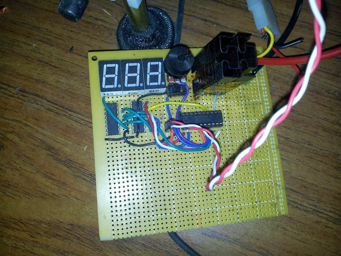
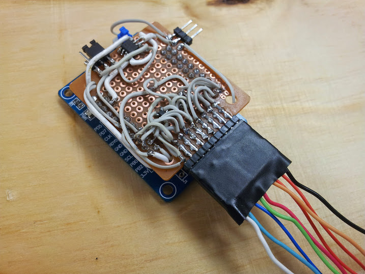
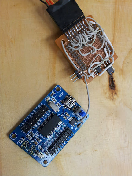
the setup that finally worked

no, it’s not cracked in half, but it does have 5 or 6 pins repaired with solid core wires.
References:
EEVblog thread with all the wonderful info (starts on page 5 or 6)
programmer I used
software I used
rest of the pictures


