I was putting one of the speaker grilles on the other day and I thought that it was pretty bad how they were retained and that I’d give that a bit of an upgrade.
This was the crap that held it on. The odd one out was obviously someone else’s fix at some point in the past, the other speed nuts were just stuck on to the padding behind the panel. No real positive retention, and they are prone to falling off or bending so they don’t retain anymore. Now for the upgrade:
That’s a 6-32 T-nut and a 6-32 x 3/4″ bolt. I ended up cutting all the bolts down because of how close they come to the speaker cone, but this is such a better option. For ease of installation I recommend you completely remove your interior trim and epoxy these in from the back side, otherwise they may keep falling out while you try to thread in. I didn’t do that but it still turned out OK.
There you have it, all the nicely threaded holes ready to accept bolts. Some needle nose pliers helped press the teeth into the plastic.
All installed, nice and neat. No more rattling screws loose.
The home page for this project is here, it has a link to the album of pictures.
This is a combination fix, I decided to replace the hatch struts so I didn’t have to haul around a stick to hold it open. That necessitated making sure I had quality hinges and replacement hinges if they failed. When I got the hatch off I found out why the defroster didn’t work and fixed that. While it was off I decided to clean up some rust and re coat the metal for protection. Finally I have touched up the primer in what should be a match to the original paint. Eventually I need new weatherstripping.
Hinges:
I got two sets of hinges from the AMC Eagle’s den facebook page. The first one had a single usable hinge (pitted) and one cracked so badly I don’t want to install it ever. The cracked one has experienced the hinge pin rusting so that it expanded and cracked the zinc casting. This exact failure mode can be equated to old restorations of the Parthenon. The second set was mostly perfect except I had to clean off some silicone that I assume a previous owner had used to seal around the body. The set I had on had one good hinge and one that had been welded back together and was porous and cracking again. I am certain that this one would have broken under the stress of new struts. I now have a backup set should my good set fail and a set that I really shouldn’t sell to anyone nor use as molds for casting. I have also noticed that the rubber seals that sit between the hinges and the vehicle are specific per side, but I don’t know why.
Good one off carStrange matte finish with crack and porosityGood partWelded/repaired partPitted partCracked partSilicone sealant residueRight one has this raised bitLeft one is flat
Defroster:
This one I noticed when I got my thermal camera. The defroster doesn’t work. I found that the cable which holds the ground wire from the defrost panel was cut because it was not routed correctly through the hole in the trim.
I see a cut in that shieldingOh, there’s the grounding strap.I grabbed some silicone insulated wire for flexibility and doubled up on the strands for current carrying capacityInsulation was pieced back together and taped together , hopefully this can be routed properly and not break again.
Rust:
On the bottom of the hatch there was some serious rust and some effort to paint over it (which was flaking off). I decided to take it all the way down to bare metal with my wire wheel and protect the surface with rust converter (converts rust to magnetite which does not propagate and is fairly hard). Once I am sure that there is no more rust I topped it with self etching primer to really try to bond to the metal. I also found a portion of the body around the plastic alignment peg hole had some rust creeping under it. To get it off I had to use a phillips bit and my new manual impact driver. The wonderful thing about that is the force that is imparted to seat the bit in the head also breaks loose the rusted threads. This avoids stripping the head of phillips screws. After all this the primer will get covered with some Mist Silver matching paint and everything should look better than new.
Rust and some lazy black paintWire wheeled to bare metalPainted and reinstalled (this will need either a new gasket or RTV after painting)Primed along the whole bottom edge
Struts:
These I picked up off Amazon. It’s a shame to see the old ones go because they’re so beautifully engineered. I particularly like the latch mechanism that keeps the ball retained in the socket. I assume the AMC logo on them either indicates they are original or at least that they are OEM replacements. The modern style retainers use spring steel curved to wrap around the outside, and the housing body is plastic. The original style is shown below. The ends are interchangeable as the ends of the strut are male threaded and that thread has remained consistent over many decades.
New struts with new style retainers old style retainer detailnew struts, old ends
The last thing I want to say is this: whoever designed the hatch lifting mechanism/geometry is both wonderful and terrible. They designed it to be maximally useful and so that the struts are not in the way when the hatch is opened. The consequence of this is tremendous force required by the struts and the stress it puts on the rest of the system. Particularly the hinges. I love that they specified such powerful struts to overcome the massive mechanical DISadvantage based on the geometry. I hate whoever designed or specified the alloy for the hinges. They’re cast and polished zinc, yet they have to carry such a portion of the gas struts’ force trying to rip them apart at all times. I took a side view shot so you can draw some diagrams of forces and puzzle over it yourself. Good idea, I commend them for that. Poor execution.
could you get less mechanical advantage out of this design? I doubt it.
The home page for this project is here, it has a link to the album of pictures.
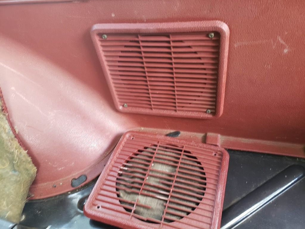
When I was working on the rear hatch I decided to take a crack at the rear speakers and grille. I researched replacement speakers that would fit exactly for a while and came up with Rockford Fosgate R1525X2 Prime 5.25-Inch Full Range Coaxial Speaker – Set of 2. I bought two sets (for the front door speakers and the trunk speakers) but will be installing the front ones later. If I recall correctly these speakers are specifically shallow enough to be install-able in the front door without hitting anything. I also thought there was a different speaker above the glove box but I believe that is if you have an AM only radio and it is a mono speaker. I will eventually get a dual coil one of those speakers for my ’57 Chevy, but it looks like I don’t need it for the AMC.
The first thing I wanted to do was replace the speaker grille, so I bought one from ebay for a dissapointingly high price and when I went to install it I decided to do the speakers at the same time. The speakers are not centered on the grille hole, which is a bit confusing at first.
why? just… why
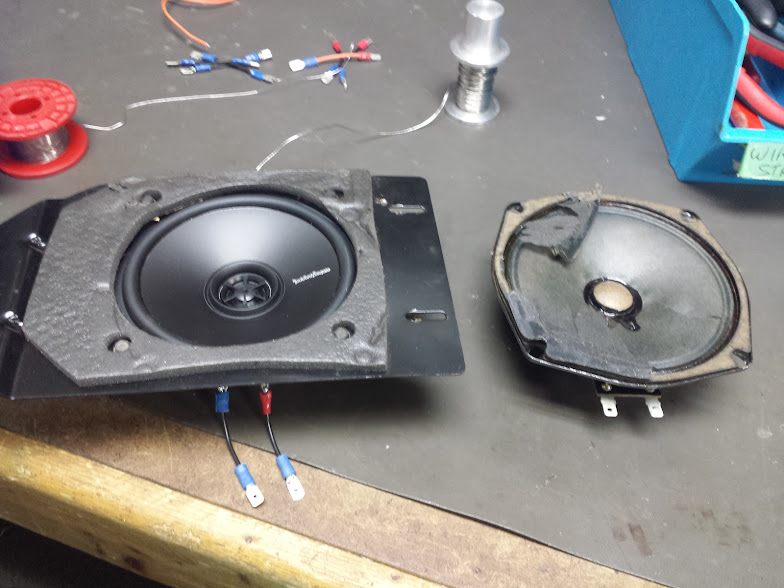
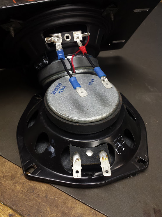
The old speakers have spaced connections at the same interval as the new speakers, but the new ones have one 0.187″ spade connector contact and one 0.110″ whereas the old ones are the more traditional 0.250″ size. I made an adapter harness to break them out to the older standard spade terminals.
New speaker installed in the plate, old torn speaker being replaced is tornNew speaker with jumpers and old speaker for comparrison
The home page for this project is here, it has a link to the album of pictures.
Some projects annoy me just because they should be easy and I can’t manage to complete them for some unknown reason. This one is not the longest time between shelving a project and completing it, but it certainly is the least work I’ve had to do to get it completed.
CPQ14USB uses the usb port shells in the current path for usb power
Side story, because apparently I didn’t blog about this when it happened. Back in high school I was working with a friend to cram a usb hub into a mouse. The idea was that we could keep a flash drive full of games or other data hidden in the mouse and it would be present as soon as we plugged in the mouse. After stripping the ports off the usb hub and adding wires to solder the usb flash drive directly to the hub board the whole thing wouldn’t power up. What I discovered maybe ten years later was that the super cheap single sided pcb for the usb hub used the mechanical shell of the usb ports as jumpers to complete the circuit for the negative wire from the incoming connection to the computer. That means that by removing the ports I broke the ground connection to the computer. That holds the record for being the longest it took me to solve some simple issue, but I’m glad I did and now I will never take for granted how someone else should have laid out their board.
unreasonably expensive for what it is
Ok, back to the main story. When I worked at GM in keyfobs we had a couple RF ‘sniffers’ that were used to detect whether a key fob was 433Mhz or 315Mhz. We could crack them open and look at the part number to determine that but this was faster and also established basic functionality (battery not dead and processor doing something). The meters we used were these (RF Solutions 006 signal strength meter) and these (RF Solutions 006-433 singal frequency signal strength meter). Imported from the UK, only displays one frequency’s signal strength at a time, and cost 100 GBP each plus shipping. Obviously being a multi-billion dollar company they wouldn’t buy one for each person to use, we had to spend time tracking each other down and borrowing/returning them because everyone needed them, just hopefully not all at once. I figured that I could just make my own so as to not need to borrow one all the time (and of course showing off was always the goal).
finished product
What do I need to accomplish my task? It needs to be pocket sized. USB rechargeable would be a nice upgrade over the 9v batteries the older ones just chugged (no, of course there were no batteries available at work, you were supposed to spend $10 in labor writing an expense report to get reimbursed for floating the company a $3 battery). Being able to display both bands at once would also be good since the existing meters either needed to switch between bands or only did one. Something analog to be able to discriminate between noise sources that may be causing interference and actual signal. You’d be surprised how much crap is in those cars that generates enough noise to swamp out the key fobs.
The first thing I needed was a couple of receivers that had RSSI out and not just a digital signal. It didn’t have to be calibrated to anything, but being able to get analog signal strength was all I cared about. That came in the form of thesetwo from sparkfun (the RWS-374-3 and RWS-371-6). They report as having a ‘linear out’ pin as well as a ‘digital out’ on the datasheet. There’s not enough smarts in them to produce voltages outside the power rails of the module so I knew the range wouldn’t be an issue for the next part.
Next I needed to be able to convert that analog voltage out into a nice bargraph display. Say hello to our old friend the LM3914, also courtesy of sparkfun. These chips are great because they have LED current drivers as outputs so you can mix and match your LEDs and you don’t even need any resistors for them. I configured mine for bargraph mode instead of dot mode and broke out the high and low reference es as well as the LED brightness as trimpots so I could just tune in the whole circuit myself. I added series resistors to the LED current setting pots to give a sensible lower limit of brightness.
The last part I needed was the rechargeable battery, that was just a standard little usb lithium charge controller and boost circuit combo board and a salvaged lithium cell that fit the case I found. The power switch came from the pile of parts (super nintendo power switch?) and the case came from the pile at i3detroit. The case already had a circular hole and I wasn’t feeling fancy enough to make another faceplate that covered that hole so it remains. Also, I’m not sure if it was extremely good planning on my part that made the PCBs fit perfectly in the case between the standoffs but it totally works perfectly. At least part of me wanted to finish this because the PCB and wiring look so pretty and were assembled so well. There wouldn’t be another use for any of these parts, too much effort to salvage anything, it’s this or the trash bin.
it works!
So, when I returned to this project all I had to do was follow the tutorial and connect pin 8 to ground (already done on one side) and connect the inputs to the linear out on the reciever modules. It just worked, I don’t know what was stopping me before. I just tweaked the low setting on the bargraph drivers so ambient noise didn’t light up any LEDs and the high setting I think is just maxed. The brightness is also at the minimum I set with my fixed resistors and everything looks great.
RF Explorer, handheld spectrum analyzer
So, that’s what I couldn’t get done while at GM. Here’s what happened after I shelved it. One of the guys in the service department that spent a lot of his time debugging RF issues had himself one of these (RF Explorer WSUB1G) and compared to what we had it just blew us out of the water diagnostically speaking. Eventually through borrowing it and months of badgering by me and anyone else that got a chance to use the one I borrowed our group purchased two of these. They still had to be lent out and one for each team member would have paid for themselves in a month with man hours lost to returning and borrowing and tracking them down but whatever, it’s something.
EL-52545 TPMS and RF tool
This next one happened only after I left key fobs and was transfered to tire pressure sensors. The EL-53545 is the culmination of over a year of work between myself, certain members of the body electrical engineering team, the service department, and ATEQ. I could spend hours talking about all the work that went into this tool, but suffice it to say when that article I linked says “Thanks to Bob Wittmann” I can attest that it wouldn’t have gotten done without his help. This tool replaced the aging J-46079 tool that used an atmel processor that was end of life and they could not build any more without re-engineering it anyway. I helped convince them to add a general purpose signal strength test to the tool which would mimic the functionality of the RF Systems tool up at the top as well as decoding the VIN stored in the key fob if it had been programmed to a vehicle. Both of these would give the dealerships much better diagnostic tools and allowed us to write service instructions where they could actually diagnose RF issues with the vehicle.
Labeled (based on the FCCID of my key fob)
Would these last two things have gotten done if I had just finished my little signal strength meter when I needed it? Probably, but with how much work it took to get those done I hate to think I might have given up if I didn’t need them so badly to get my own work done.
This is one of those things that you just have to do because the factory solution is crap. Apparently this was notorious back in the day, AMC just couldn’t make their plastic valve cover seal at all and it always leaked. I can see why, the flange bolts trying to clamp down on the edges of a flexible plastic lip that’s really small is a terrible idea. All that being said there are some hurdles and some of what I think are terrible ideas for how to actually install your aluminum valve cover that I’ll go over here.
keep crap from getting down there
First is to label all the vacuum lines and wires that cross the valve cover that you disconnect. I recommend masking tape flags with numbers because I used metallic sharpies and still can’t figure out where they’re all supposed to go. Second is that when you remove things like the PCV elbow that sticks in the back of the valve cover, remember where you put it. The auto part store does not have an exact replacement any more and you’ll have to grind it down a lot until it fits. Third is to plug all holes where the push rods go with excessive shop towels, seriously nothing should get down there and if it tries you should gently vacuum it back out.
scotchbrite scrubbed
After you remove the valve cover I recommend scrubbing the surface with a scotchbrite pad soaked in mineral spirits. It will help get any oily baked on gunk off so the new gasket can seat. Once it’s clean you can then get ready to tap the two un-tapped holes. Originally I think these were used for locating pegs in the plastic valve cover. Some people have reported that you have to drill them out to a certain size and tap them for 1/2″-13 bolts. The kit I got had 5/16″-18 socket cap bolts for all the large holes so I tapped them for that. The holes were already large enough to take that tap without drilling (it had me a bit nervous that it would be too sloppy). I first ran a regular tap, then a bottoming tap, the top of the hole has a slight chamfer so a starting tap really isn’t needed. Be gentle so you don’t strip them out, but be sure to go all the way to the bottom. When I did this I had circular ring magnets stuck to the head so the chips stuck to that and I still vacuumed out the remaining bits. You can also use a thick grease to catch the chips, but cleanup will be harder.
thin metal tubing taped to the end of the vacuum will get down in that hole to clean it out, that and brakleen
When installing the gasket I used a generous portion of high tack gasket sealant on both sides of the cork gasket, it was really helpful in keeping it in the right position when tightening because some of these edges are very thin. If at all possible install this valve cover on an engine out of the vehicle. The clearance between the firewall and the head is not that big and I had some trouble squeezing it in there, but it can be done. The paint on the back of my valve cover is now a bit scraped up but you can’t see it anyway and the aluminum isn’t gonna oxidize any more because of it.
this works rather well
The only trouble I had when reinstalling the cover was the rear bolt. It’s one of the 1/4″ ones and getting a hex head in there to tighten it was almost impossible, getting a torque wrench on? how could you even do that? Well, as you can see, through a series of adapters I managed to get my torque wrench on a flex shaft and on to an allen head socket adapter all seated and torqued down. There are instructions that will tell you to drill a hole in the metal lip over top of the bolt, but that’s the tray that carries rainwater away from the cowl, you can’t just have holes in that. This is a far superior method for tightening that last bolt. After all that effort, did it work? does everything look and run smoothly?
Oh yes!
This thing will eat years old gas through a rusted out hard line and just not give a crap. I think I stripped out one of the aluminum tapped holes where you mount the solenoids but I can drill and re-tap that for a bigger size. Be aware that the bolts they ship that with may be too long so don’t force it, just add washers or grind down the bolt.
This one was a bit of a challenge. The ifan02 uses relays and capacitors to do speed control just like the way the special pull switch does on dumb fans. The trouble is, I don’t know what about adding capacitance to some winding on a motor makes it go faster or slower. The fan I have uses 6.5uF capacitors and the sonoff comes with 2.5uF ones onboard so I have to change them to make it compatible. I think I got lucky with this one.
The switch in question
The main problem is this: the fan I have has one big monolithic capacitor that has three components in it, two of which get switched out for changing the speed and the other I think is the ‘run’ capacitor and is always connected to a special winding on the motor. I don’t have room to fit the ifan02 in the part of the fan where the switches are normally located, between the fan and the light. This means I need to put the module above the fan, in the ceiling. I also need to transplant 2/3 of the capacitor into the ifan02 because my fan uses different value capacitors than the ones onboard the ifan module. Luckily for me the 5uF of run capacitance is exactly double the 2.5uF capacitors in the ifan, so when I remove those to install the 6.5uF ones, I can make a 5uF capacitor from the leftovers and stuff it where the old one was.
I hope this makes sense to you, it sort of makes sense to me.
I started to puzzle out the pattern of adding capacitors and how many made what speed, but it turns out that it’s already done by defining your module as a SONOFF_IFAN02 in tasmota. There’s special code that handles different speeds and the light separately. Internally I’m not sure how it works, but there’s an RF remote that works in parallel with the network control of the fan and light. That remote takes a CR2025 battery, but will work with a CR2032 if you force it. You also have to re-pair the remote after changing the battery, there’s a switch on the back of the PCB for the remote you can use.
Initial puzzling
After it was online, it had to get integrated into homeassistant. I did that using the “Fan Control Entity Row” installed via HACS which is like an outside repository of integrations and UI components. You need almost the latest version of homeassistant to do that so once I got done updating and installing all the dependencies I had to figure out how to write the yaml component. After a lot of checking with different people’s solutions I ended up with this:
There is one quirk I think I found, if you power cycle the module and then don’t command it to do anything the light will come on (good), the fan will come on (good?) but the fan speed seems to change and it doesn’t beep to indicate it’s doing so (not so good). I don’t know if this is some strange mode that the micro-controller (not the esp) onboard is in, or if I’m imagining it but I now always assert the fan speed shortly after power cycling the module.
Years ago I heard about the OpenDPS project to give open source firmware to cheap and available chinese power supplies. These aren’t strictly whole power supplies, they are configurable CC and CV buck converters. That means that it needs a stable DC source to back it to be used as a bench power supply. Perhaps you may not want to do this if you intend to use the DPS as a battery charger run from a solar supply or something, but most people I see want to use them for bench supplies so that requires an existing DC supply. Today I finally finished mine.
I chose to start with the DPS3215 meaning it’s capable of 32v output at 15a max. The sheet that came with it said to give it 36-40v as an input so I got myself a 36v 11a switching power supply for about $25. I cranked the fine tuning pot all the way up and now it’s a 38.something supply, but I’m regulating it later so who cares. Now that power supply had a 12v fan inside hooked up to some sort of thermal or load dependent fan speed controller. Since I’m putting this whole thing in a bigger enclosure I took the opportunity to remove the fan from this aluminum box, chop the connector off it, attach a slightly bigger fan, and bolt it to the inside of my new power supply enclosure. I also punched a big open hole in the side of the power supply so we can get some more airflow, no need to protect from fingers now.
one input hole, one exhaust (no fan)
I happen to have a couple greenlee punches, tools for cutting a really nice crisp circular hole. The trouble is they only go up to 2″, and my fans need a lot more than that to get decent airflow. The method I used here was to lay the fan grill on the enclosure and use a scribe to trace one of the circular lines (although I didn’t use the largest one). Then I step drilled out a big enough hole and followed up with the good old jigsaw with a metal cutting blade. It’s not a super pretty cut, but it works very well. Cutting rectangular and trapezoidal holes for the front panel and power jack were also pretty easy using that method, and the rest are just drilled out to size. The power supply had tapped holes in it to bolt through and the banana jacks/binding posts are all EXACTLY 0.75″ center to center. I added an earth ground and couldn’t decide where it should go relative to the other two so I made it an equilateral triangle.
I had a solder bridge under the plastic standoff
Flashing this power supply gave me some trouble, it’s not explicitly called out as compatible so I did some tracing and after clearing all solder bridges I determined that from left to right V = Vdd (power), <no marking> = no connect, S = VSS (gnd), C = Clock, D = Data for the st-link programmer. That worked great. The other header for serial is labeled correctly with tx, gnd, and rx.
Some notes about flashing/building the firmware for the DPS3215 specifically:
The dpsctl.py script is specifically python3, it doesn’t seem to be called out anywhere as that so I changed the first line to force it to use python3.
This power supply is subject to the this issue and needs a different chip select defines when compiling, so treat it like a DPS5015.
I had an issue with currents over 9.99A (the number of digits was fixed, it rolled around to zero). That’s apparently a variable that can be set at compile time but the functions for CC mode, CV mode, and CL mode needed to be tweaked to accept those values and not just be stuck at 2 digits and 2 decimals. You can see in this header file you’re supposed to be able to set all these things dynamically, but the functions above in this revision of code don’t use them. You will also see the max current, I set mine to 10A, it could probably go higher but that seemed enough.
Calibration Report:
A_ADC_K = 4.377185344696045
A_ADC_C = -260.4835205078125
A_DAC_K = 0.25430262088775635
A_DAC_C = 263.3804931640625
V_ADC_K = 8.133505821228027
V_ADC_C = -109.9773178100586
V_DAC_K = 0.1118573322892189
V_DAC_C = 8.37867546081543
VIN_ADC_K = 16.66666603088379
VIN_ADC_C = 118.33333587646484
VIN_ADC = 2305
VOUT_ADC = 14
IOUT_ADC = 0
IOUT_DAC = 0
VOUT_DAC = 0
calibration report for my unit, you may want to do your own
Unfortunately the calibration report put out by the python script cannot be fed back into the python script as it outputs with spaces around the equals sign and the script only accepts parameters with no spaces around the equals sign.
That’s it, I now have a working power supply neatly packaged. I wouldn’t say it’s the easiest thing in the world to flash and there seem to be some things that have been identified but need cleanup in the master branch on github (but at least they acknowledge them in the issues section so you can find them yourself. I never actually found out how you’re supposed to specify model and the compiler will pick based on options you set, I just hacked up the code so they were all what I wanted for my supply. Not ideal, could use some cleanup, but I made it work.
This is a post I’m writing mere minutes after completing the last bit (a rarity). Months back a friend bought one of those yellow chinese ‘component tester’ modules from ebay, at the time of writing they can be had for $12.85 USD OBO. It came with a broken screen so you could only see a portion of what was being displayed. He got a replacement, but I took the broken one and intended to buy a replacement LCD and fix it. I bought a replacement ST7565 breakout board for $6.99 USD. After much continuity testing and board tracing I came up with this pin layout for the pads the flex ribbon on the LCD used to be soldered to:
I traced the pins to ground, power through some diodes to drop the voltage, some caps, and PD0-PD4 on the atmega. This at least told me I was dealing with 4 data lines. I tried some naive wiring permutations but eventually I checked them with a scope to come up with the guesses of Data, Clock, Enable, and RS. After much more fussing I gave up and resorted to actually research the project that the chinese copied for clues. Here’s where I find all the information I needed.
from the master project document that shows lots of variations
First I find the hackaday article on someone converting the transistor tester into a display for his car (proving that this product is SO cheap that it’s the most economical way to buy this screen and microprocessor together. He has a schematic so I didn’t have to do all that tracing. Next I find this master document on the transistor tester that directly calls out the pins I need to connect because they all apparently use the same codebase (clone or otherwise). So I connect it up and….
um…
It’s backwards. According to the guy who ported this game thing to the transistor tester hardware you have to flip the Y direction for the screens used on these. Which means a normal screen is flipped when driven by one. Great. All that work and now it’s flipped. I also found out that apparently now I have to hold the button to make it work. I think there’s supposed to be a keepalive transistor (on PD6?) that the mcu can use to give itself power after the initial button press, and mine might be blown. I can probably trace that but now I’m stuck rebuilding the code and reflashing it to work with my screen. This was supposed to just be soldering some wires and boom! working unit.
Years and years ago I bought some bench meters from a blind auction at my friend’s work. These meters all checked out perfect, I personally tested the calibration against some calibration samples we had at i3 and every single digit was spot on for every meter. The only problem was that the meters were missing the carry handles/stand thing like they had been installed in a rack setup. That’s not an issue, but all of the plastic around the meter face was broken. This means that there was no longer any way to secure the face to the meter body. My usual repair methods don’t work here, there’s nothing good to superglue, epoxy, or solder. Hot glue would work but you’d have to melt it off to change the fuse and that’s just stupid. This is the first time I’ve repaired something this way and it’s not revolutionary, but to me it made for a super solid fix with almost no effort. I drilled and tapped holes through the plastic face and metal frame for 4-40 bolts. 4 bolts per meter and they are solid as ever. Having some drill bits and taps can make repairs pretty darn easy.
Cleaned up and ready to go (the bottom one had enough plastic to just bolt back together)
I also had to superglue some cracked plastic on the back panels so the screws could hold the plastic to the metal frame. They clean up good, they might even warrant some rubber feet from the hardware store screwed into the bottom of the case.
I’ll admit, this one’s a bit pointless. It’s because I had to buy the connectors for my test box harness in pars of male and female connectors. I had nothing else to do, so I thought I’d put together a simulator to exercise the test box while in the comfort of my air conditioned home.
The circuits are pretty simple, everything except the o2 sensor go through some dual Nfet bidirectional voltage level converters (super cheap on ebay or wherever) and that allows the arduino mega which is powered by 12v to send 12v signals to the box full of LEDs and whatnot. The o2 sensor is sent through a voltage divider and even then since I didn’t get it right I don’t sweep all the way up to the max value PWM. The tachometer uses the ‘tone’ function in arduino to output a square wave of a given frequency to simulate engine speed (this will help me calibrate the tach as well). That’s really it, I decided to blink each LED once in succession to show they all work and none are shorted. Once I have verified my richer/leaner circuit on the running engine I’ll set this thing up to simulate that pattern to test that circuit as well.
the ink of the datecode bled through the paint
The whole thing fits into a repurposed dishwasher soap box and all connections are made through the lid. The code is up on github here.