Archive for the ‘home automation’ Category

Eco Plug (ESP8266) hack, finally!

March 16, 2017

This has been a very long time coming. I first heard about these outlets more than a year ago via reddit and was intrigued.  This is a very convenient form factor for an ESP, a power supply for it, and a relay to control something via mains.  This was before the prevelance of the sonoff (wiki) or electrodragon (wiki) modules that are now so cheap and with some digging I found out that these ‘generic’ modules that were being carried by Home Depot, Walmart, or wherever you don’t expect to buy ESP modules had power monitoring in them.  The actual manufacturer of these parts is KAB Enterprise Co., Ltd and through their website you can see all the different modules they make and some names that will help you google for sellers of them (even a wifi in-wall switch).  All of the wifi devices are basically an ESP with some other circuitry that you may have to reverse engineer or bypass (like I did).  You can find these at Walmart (or probably just their online store).  There are some deal sites that have found these for very cheap prices but even then you may want to just buy the sonoff POW to be sure you have power monitoring with no major modifications.

Chip to be bypassed still present, module removed

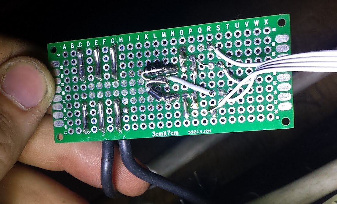
module back side (I toasted it)

Reset switch unpopulated (I added one and drilled a hole) and chip to be bypassed remoced

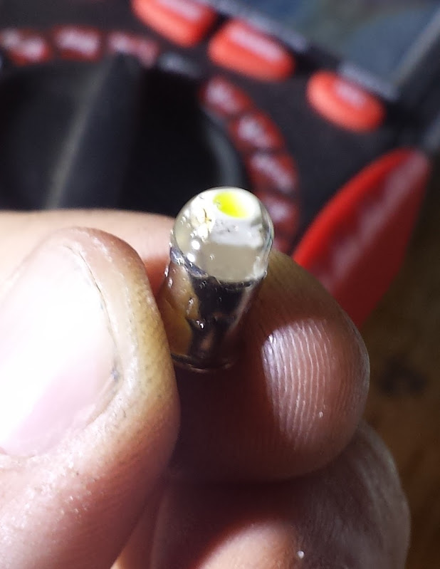
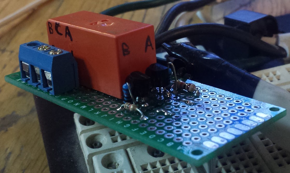
As the KAB website shows there is a difference between the CT-065W and the CT-065W (Advanced) in that only the advanced one has power monitoring capability.  This is apparent if you look at the other reddit thread and have people with modules that have additional components on them.  It was discovered that the power monitoring IC is the hlw8012 that was not terribly well known (to me) until the POW came out.  The extra hoop the CT-065W (Advanced) modules have is that they have an extra chip in there, labeled on the underside (discovered by the person who always saves my ass), called the 1588NAZ04 and there has been some efforts to reverse engineer it in the comments section here.  I took the pinout from here and tweaked it for how I modified my plugs, it is the same pin numbering as here.

1 GND
2 Power 3v3
3 CHIP_EN reset sw
4 XPD_DCDC / GPIO16 PF HLW8012 CF power
5 MTMS / GPIO14 VS GPIO05 HLW8012 Sel output
6 MTD1 / GPIO12 VC HLW8012 CF1 voltage / current
7 MTCK / GPIO13 power sw
8 MTD0 / GPIO15 Y to main board , D8 (power)
9 GPIO2 D3 (wifi)

10 GPIO0
11 GPIO4
12 DVDD / GPIO5
13 U0RXD
14 U0TXD
15 RST
16 GND
17 TOUT / No Connection?
18 GND

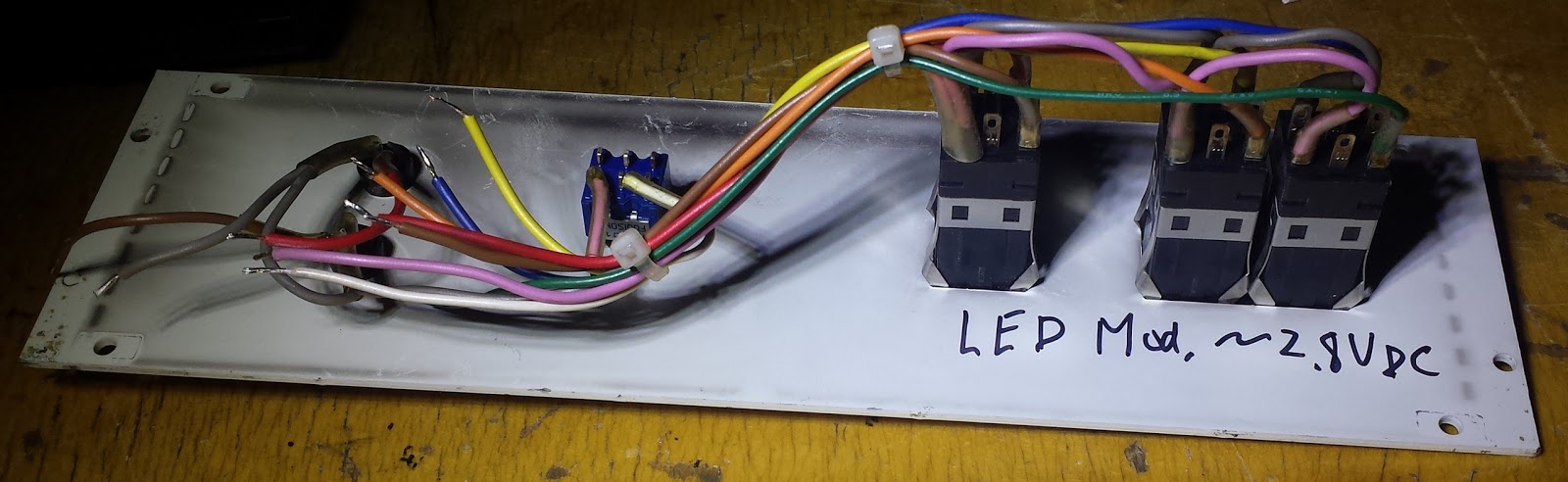
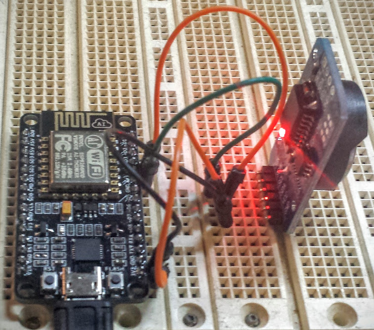
I decided that for my modules I was going to just outright remove the chip and use some of the many extra pins on the ESP module to talk to it (indicated in red above), this basically converts it into a POW with a different mapping.  My main motivation is because I have come to really like this firmware, partially because other people already use it and it’s very easy to configure.  With my use of these modules for OpenHAB I really needed these modules to be stable and flexible.  There are other firmwares that people have used on this device (or family of devices, really) but I have my favorite.

Flashing harness, I had to add an esp-12 because I toasted the original, this is not an upgrade, just a repair by me (look closely and you can see that I wired to the pads of the chip I removed)

For flashing these modules I used this other firmware‘s tutorial which worked flawlessly.  The modifications I made to the firmware to add my own hacked outlet module definition was quite easy, it just involved extending a couple tables in the sonoff_template.h file and giving my variant a list of pins and their uses.  I have included that section here:

/********************************************************************************************/

// Supported hardware modules
enum module_t {
CUSTOM_OUTLET,
SONOFF_BASIC,
SONOFF_RF,
SONOFF_SV,
SONOFF_TH,
SONOFF_DUAL,
SONOFF_POW,
SONOFF_4CH,
S20,
SLAMPHER,
SONOFF_TOUCH,
SONOFF_LED,
CH1,
CH4,
MOTOR,
ELECTRODRAGON,
EXS_RELAY,
WION,
WEMOS,
MAXMODULE };

/********************************************************************************************/

#define MAX_GPIO_PIN 17 // Number of supported GPIO

typedef struct MYIO {
uint8_t io[MAX_GPIO_PIN];
} myio;

typedef struct MYTMPLT {
char name[16];
myio gp;
} mytmplt;

// Default module settings
const mytmplt modules[MAXMODULE] PROGMEM = {
{ “Custom Outlet”, // modified eco outlet (ESP8266)
GPIO_USER, // GPIO00 Optional sensor
GPIO_USER, // GPIO01 Serial RXD and Optional sensor
GPIO_LED1_INV, // GPIO02 Blue Led (0 = On, 1 = Off)
GPIO_USER, // GPIO03 Serial TXD and Optional sensor
GPIO_USER, // GPIO04 Optional sensor
GPIO_USER, // GPIO05 Optional sensor
0, // GPIO06 (SD_CLK Flash)
0, // GPIO07 (SD_DATA0 Flash QIO/DIO/DOUT)
0, // GPIO08 (SD_DATA1 Flash QIO/DIO)
0, // GPIO09 (SD_DATA2 Flash QIO)
0, // GPIO10 (SD_DATA3 Flash QIO)
0, // GPIO11 (SD_CMD Flash)
GPIO_HLW_CF1, // GPIO12 HLW8012 CF1 voltage / current
GPIO_KEY1, // GPIO13 Button
GPIO_HLW_SEL, // GPIO14 HLW8012 Sel output
GPIO_REL1, // GPIO15 Red Led and Relay (0 = Off, 1 = On)
GPIO_HLW_CF, // GPIO16 HLW8012 CF power
},
{ “Sonoff Basic”, // Sonoff Basic (ESP8266)
GPIO_KEY1, // GPIO00 Button
GPIO_USER, // GPIO01 Serial RXD and Optional sensor
0, // GPIO02
GPIO_USER, // GPIO03 Serial TXD and Optional sensor
GPIO_USER, // GPIO04 Optional sensor
0, // GPIO05

For right now that’s it.  The configuration for this firmware is deep and takes some looking but I feel like I could implement any sensor I want in their framework with a small effort.

The rest of this series can be gotten through from the home page here.


Amazon Dash Button Re-Hack!

July 14, 2016

So, we just got through Amazon Prime Day.  That means I got myself a handful of amazon dash buttons for $0.99 each.  How could I resist, I could do some coding in a new toolchain and architecture I’m not familiar with… ok no.  All I intended to do with these was to use the software-only hack that allows you to capture the button presses and pipe that through to my mqtt server.  Amazon decided to thwart me just a bit.

As noted in this wonderful teardown there’s a new kid on the block for amazon dash buttons (JK29LP).  The old one (JK76PL) had an stm32, the new one is an atmel.  I would normally like this, but no one else has blazed a trail for me yet so I’ll fall back to being lazy.  The new amazon dash buttons no longer broadcast the message that the original hack picks up, but I tweaked it and am back in business (although from the blink pattern you can tell what revision button you have).  There’s a new program someone wrote to have a windows daemon that runs a program or script whenever a button is pushed, and it even works on the new buttons.  But it only works on windows and I just won’t have that.

I based my work on the original code from a number of different places used for different purposes.  My modification is using the dash button to send out a message on a given topic on a given mqtt server (in my case it’s localhost).  I thought that if the windows program used the ip addresses that the router gave leases to then I could get the MAC addresses by checking the leases in my router.  If I had only been smart enough to remove this line:

if pkt[ARP].psrc == ‘0.0.0.0’: # ARP Probe

I would have seen the buttons being pressed.

from scapy.all import *
import os

def arp_display(pkt):
if pkt[ARP].op == 1: #who-has (request)
if pkt[ARP].hwsrc == ‘f0:27:2d:ef:a8:a2′: # ARP Probe
print “ARP Probe from: snuggle 1 ” + pkt[ARP].psrc
os.system(“mosquitto_pub -h localhost -t displayTopic -m snuggle1”)
if pkt[ARP].hwsrc == ’74:75:48:6f:3b:b7′: # ARP Probe
print “ARP Probe from: snuggle 2 ” + pkt[ARP].psrc
os.system(“mosquitto_pub -h localhost -t displayTopic -m snuggle2”)
if pkt[ARP].hwsrc == ’44:65:0d:78:94:12′: # ARP Probe
print “ARP Probe from: glad 1 ” + pkt[ARP].psrc
os.system(“mosquitto_pub -h localhost -t displayTopic -m glad1”)
if pkt[ARP].hwsrc == ’44:65:0d:c6:e5:21’: # ARP Probe
print “ARP Probe from: glad 2 ” + pkt[ARP].psrc
os.system(“mosquitto_pub -h localhost -t displayTopic -m glad2”)
if pkt[ARP].hwsrc == ‘0c:47:c9:7c:55:20’: # ARP Probe
print “ARP Probe from: redbull 1 ” + pkt[ARP].psrc
os.system(“mosquitto_pub -h localhost -t displayTopic -m redbull1”)
if pkt[ARP].hwsrc == ‘0c:47:c9:ed:9c:46′: # ARP Probe
print “ARP Probe from: redbull 2 ” + pkt[ARP].psrc
os.system(“mosquitto_pub -h localhost -t displayTopic -m redbull2”)
if pkt[ARP].hwsrc == ’44:65:0d:4d:a6:0b’: # ARP Probe
print “ARP Probe from: burt’s bees ” + pkt[ARP].psrc
os.system(“mosquitto_pub -h localhost -t displayTopic -m bees1″)

print sniff(prn=arp_display, filter=”arp”, store=0, count=0)

My code hardcodes the MAC addresses without checking for a 0.0.0.0 arp packet and prints out to the terminal and sends a mqtt command.  I run all this on my mqtt server pi and have it autostart just like the screen script.  Except not just like that because I want this one to run as root since I can’t do permissions worth a damn.  That would be here, and I’m still working on it.

I know this isn’t original as I see references to people removing that line, but I see no reference to the new dash button and this rock solid implementation of the year old python code.  That being said I also haven’t seen this tied to mqtt either, so that may be original.  NOTE: this triggers a notification on the amazon shopping app everytime a button that does not order a product is pressed.  This could be mitigated by blocking access to amazon’s servers for those buttons but I just sign out of the amazon shopping app (I could set them back up using a fake account, but it’s late).  I also like the thought of finding out how to respond to the buttons so they blink green when amazon responds, but I’m not willing to dig into that right now.

ESP8266 control panel upgrade

June 20, 2016

While writing the article on multiplexing the esp’s inputs I came up with the idea of PWMing all the outputs at once by interrupting the path to ground with an n-FET.  That’s actually not a bad idea, and I have an extra input on the analog MUX that I can use for a light sensor so I can even have auto-dimming.  This is to describe how I did that.

play spot the difference!

With much difficulty and frustration.  That’s how I did it.  If you hadn’t figured it out yet I wrote the intro to this piece before actually preforming the task.  The main problem is that for some reason I couldn’t get input 0 of the analog mux to do anything.  As I think about describing my problem here I also may have the solution… fuck.  The problem is that any input to that input was pulled very very low to the point of pulling more than an amp at a half a volt.  I swapped the chip but it continued to happen.  What I didn’t do was check for a little solder bridge (would have to be very little) to ground which could be what caused the pull down and uselessness of that input.  In order to get around this I added another control line for the mux to use the other inputs.  An act I now realize could have been to move s0 to s2 and tie s0 high so I had to use the other bank of inputs…I was having a good night until I go to write it down, I swear.

So, with a cadmium sulfide cell acting as half a resistor divider I can read the local light level.  That information could be used to dim the LEDs if I had that ability.  It turns out that when I wired the LEDs I tied them all to the same ground wire, one not shared by any other things.  I decided to break the ground wire just before it hit the ground plane and stuck a 2n7000 FET with pull down resistor on it.  This is called “low side drive“, a technique I have paired with individual”high side drive” pins coming from the ‘595.  Since the shift register can only update all of the LEDs at once I decided that PWM through SPI is more convoluted than I want to write code for.  The reason I want dimming is so if I mount this on a wall in a room of my house I can have the LEDs not be obtrusive while still being visible.  That means all I need is to dim them at once so I spend an extra output to control the brightness of all the LEDs at once.

That sums up all the hardware changes I made, if you take a look at the code you will find that I have put in a lot more commands, I have moved some things out to functions, and that I have defined masks for reading/writing bits rather than having hard-coded sequences.  I rather like my new code, but one thing I’m going to move toward is having many topics on each device. The problem with defining the topics now is that if I don’t know where I’m going to put things or how I want them to interact then I can’t design a system.  The problem I face as being not-a-programmer is that I don’t know a good way to parse the payload of a message.  What I have right now is to have a lot of verbatim answers or an’else’ which I use for numbers.  First: I should move to a switch/case structure, and second I could stand to parse a smaller part of the payload making my code more versatile.  I’m not going to do the second one,I will instead move to a lot of topics which contain ‘/’ symbols so it looks like a hierarchy even though it isn’t.

here is the bit of code I updated.

here are the pictures (again).

here is my hub for all things esp8266.

ESP8266 control panel (input muxing)

June 10, 2016

So, I got a housewarming gift in the form of some pieces from an SEM control panel (it really is the people you know that helps).  My default answer these days is to adapt the controls to an esp8266 and throw it on mqtt.  This turned out to be the perfect project to show off the multiplexing capabilities of the esp8266, or put another way, how to mux your inputs to work on a microcontroller with very very few inputs.

This control panel is kinda cool in the fact that it has 3 lighted buttons, 3 toggle switches, 1 LEDs, and 3 analog controls so that no matter what you want to control it will probably work pretty well.

The first thing I’ll cover is the analog.  The ESP8266 only has one analog input, and that is limited to 1v.  I don’t know why that is the case considering the rest of the esp is a 3.3v device, but it just is.  It’s better than being a higher voltage since you can always apply a resistor divider to the ADC and sense a larger voltage, but sensing a smaller voltage requires amplifiers which are more complicated and prone to noise and power concerns (power concerns says the guy who just suggested burning off power over resistors).  The ADC is 10bit, which seems to have become standard on microcontrollers these days even if you usually only see 8bit pwm.

So, how do you use a pot on a 3.3v microcontroller as an analog input to a 1v ADC? more resistor dividers! A potentiometer has 3 pins (usually) being either end of the piece of resistive material and a center tap which selects the ratio of resistance.  This means that a potentiometer can be though of as a variable resistor divider (or a resistor divider can be used to replace a potentiometer if you need a fixed value).  Normally I would hook the outside legs of the potentiometer to the power rails and the wiper to the analog input, but in this case giving between 0 and 3.3v to the ADC is not desirable.  There are two ways to accomplish what the esp needs, you can either change the reference voltage for the potentiometer, or you can scale the input to the ADC.  I chose to scale the input to the ADC because I have 3 potentiometers and want to keep the analog voltage as high as possible until the last possible moment to shrink the impact that noise has on the signal.

That was how to use a POT to drive the ADC on an ESP8266 (acronyms and abbreviations get thrown around a lot, don’t they), but how do we use 3 of them at once? There are multiple answers to this question, and continuing cheapness of i2c chips make the economics not as clear as they once were.  My tendency is to use the least number of chips, and the least complicated ones to do the job.  In my experience this leads to easier debugging (thy do you want to worry about high-speed signal capacitance when all you’re doing is reading a POT with an MCU?).  For this I chose the 405X.  The 4051, 4052, and 4053 are different combinations of analog multiplexer (4051 is a 1:8, 4052 is 2 1:4, 4053 is 4 1:2).  Since I have one analog pin and 3 sources of analog voltage  I could use the 4051 (and have unused inputs) or a 4052 (and have an unused mux and one unused input).  Driving them is identical (tie unused address lines high or low, just be consistent) so it doesn’t matter which I used (check the pictures, I’m writing this before taking them).

Now, before we talk about the outputs let’s talk about the switches themselves.  These are fairly nice switches, they pop out, have inserts for text, easily replaceable bulbs… Bulbs. Nope, those have to go. It’s not just that they are less efficient than LEDs, but they’re also something like 28v bulbs which is just not reasonable to have to step up the voltage for. If you’re doing this with precious vintage equipment that you can’t bear to modify then I’ll recommend a step up converter and some FETs. I broke the bulbs, soldered to the filament, and potted with hot glue. It seemed like the easiest way to add LEDs without messing with the mechanical beauty of the switches.

The LEDs also need current limiting resistors, I picked ones that put out a reasonable amount of light and work with my 3.3v power supply.  The choice of LED was ‘what looks good that will fit and I have lying around’ and the choice of resistor was ‘what works with that LED’ so you need to pick your own for LED-moding your electronics.  The resistors I put in-line with the input to the bulb socket and heatshrunk over.

So, now let’s deal with the outputs for these panels.  The white LEDs I just explained, how I set them up to be driven with 3.3v, but we also have 2 red LEDs.  The red LEDs had both positive terminals wired together and apparently used low side drive to switch them, I decided to make all the outputs on this project high side drive so I unwired the LEDs and rewired them with resistors that make them pleasing to look at at 3.3v (as I do more projects I care less and less what amperage my lights are, they just need to be ‘pleasing’ and ‘not going to burn out’.  Since these LEDs are driven over shift registers I can’t use the hardware PWM to control the brightness, it’s important to choose a light leven that is comfortable because it will be hard to dim (although one could low side drive the common light ground to dim them all as one).

The chips I chose for input and output were a complete pain.  There are so many complimentary parallel-serial chips it can get overwhelming picking them.  The 74xx595 and 597 are very modern and the go-to standard of many hackers (including myself) but they have extra control lines for the latches which means they can’t be used with just hardware SPI.  The 74xx164 and 165 are closer but they are still not exactly right.  I eventually settled for the 74HC595 and the 4021.  I really don’t think I should have to mix families to accomplish this, and I couldn’t tell you exactly what the problem was anymore with the other chips, but using this combination I can use hardware SPI commands and it works every time.  Credit goes here because I would never have thought of that.  The difference in my design is that I decided not to waste any cycles and I wired the SS pins together so every time I read the input I update the output (well, I could but didn’t if you check the code).

Now, just to make sure everything’s consistent I recommend you pull all the buttons and switches either up or down (be consistent) and have them connect to the opposite rail on activation.  You may think that I wouldn’t need a pull down resistor with the toggle switches and I could have definite states for both positions, you would be right but I decided not to add any more wires so that means only two wires per switch.

There you go, that’s how to multiplex analog and digital signals with some basic logic chips so your esp can control more things.  Of course there will be people that think everything should be done over i2c, but there are serious problems when trying to do fast input and output on a shared bus.  I’m already planning another couple features before I call this done so you may see it again soon.

I’ll close by saying that I’m leaving this a bit open-ended.  There are so many things you can do here I won’t try to write a firmware that works for them all.  I was originally thinking this could be a thermostat, but now I’m leaning more toward a lighting controller (light intensity, warm and cool tint knobs, indicator to see if the lighting has been overridden, buttons to control the rest of the first floor lights).  Whatever it becomes I now have example code to chain as many parallel inputs, outputs, and analog inputs (you can run the multiplexer off the 595 if you want) into an ESP8266.

code is here or here.

pictures are here.

The rest of this series can be gotten through from the home page here.

little esp modules

May 28, 2016

I really like these little modules, they can be had very cheaply from aliexpress.  They have a CdS cell, an RGB LED, a micro usb port for power (and linear regulator that can run the module) and a button on them.  They come with a little programming board with a CH340 usb-serial converter, and reset/flash buttons.  The reset button wiring is pretty obvious.  The button on the esp board goes to GPIO4.  The ‘flash’ button goes to GPIO0.  The RGB LED goes to pins 15, 12, 13 active high.  The little blue led on the module is tied to GPIO2 which is why it blinks when programming.  The CdS cell is tied to the analog pin, it spits out between 50 and 1024 (basically the whole range). They program exactly like a nodemcu 1.0

The rest of this series can be gotten through from the home page here.

auto-display ip address on a raspberry pi

May 28, 2016

Here’s a quick one.  I like using a pi as a server for things like mqtt, but with my experimentation I bring it back and forth between home and my local hackerspace.  Now, sane people might use DNS to find the mqtt server, I had trouble with that and gave up.  I can usually guess the ip address because the router holds on to the one it gave me last time, but that doesn’t always work.  Here’s how I decided to have the headless pi tell me the ip it is connected at.

I tried doing this with an HD44780, I have seen people do it with a 10k pot and no other electronics between the pi and display.  I tried for a day and couldn’t make that work.  My next option was to but a display on a breakout board for the pi, then I can’t doubt my wiring and it either works or it doesn’t.  It turns out that a nokia 5110 display is really cheap on ebay, so I looked around briefly and figured that I could get it working when it came in.

Here’s what I found:

the unit I got was wired to gpio that is not on the hardware spi bus, but the pins seemed the same as the one described in this article.

That means using the adafruit libraries described here.

The contrast sucks with the initial image test, but the text looks ok.

I needed to get my ip address in python, I used netifaces as described here.

That broke when there was no cable plugged in, so I caught the exception like this.

I wanted the hostname as well, so I used socket, like this.

I wanted it to start on boot so I used rc.local as found here.

my final code is located on my github here.

ESP8266 RTC and NTP

September 24, 2015

This one’s a doozy.  Maybe not to read, or write, but to code it was by far the most ‘fun’ so far.  My decisions at the time may have been lost to the sands of time, but I will try to capture them here as best I remember.  Let’s start with NTP.  NTP is very good for setting a clock, but it takes a call out to the network, and a response back along with a bunch of calculation you’ll see later to get a good time out of it.  NTP is not suitable for repeated hammering if you want to append a time to, say, a log file.  a Real-Time Clock is great for keeping time (just like your alarm clock) but not so great if you have to set it.  You could send an offset to move it up or back a certain number of minutes, hours, whatever if you need to set it, but we’re already on the network so why not do it automatically.  The code I write can work so much faster than I can and synchronizing clocks is not really something to be left to ‘eyeballing it’.

The most common RTC is the DS1307, it’s everywhere, like popcorn almost.  The chip I ended up using however was the DS3231.  In case you were wondering, the DS prefix is a holdover from when Dallas Semiconductor used to make them, they were bought by Maxim and that is where you can see new products coming from.  The DS3231 is more accurate, but most importantly for me is that it will run off of 3.3v.  You can see one of my favorite blogs go over how to use them here, my use case was getting it set by NTP, then using it to timestamp data.  The ESP is supposed to have an RTC in it, but it uses a pretty bad oscillator, even then I don’t know how to use it.  For this project I elected not to unravel the use of RTC libraries to write one for the ESP specifically and rather just use an off-the-shelf one.

The first challenge I had was getting the clock to read.  That code was taken blatantly from a library’s example and trimmed down to accommodate what I needed.  It included a bunch of checks to see if the time and date coming from the RTC made logical sense, which is useful when you’ve got a 50/50 chance you wired up sda and scl correctly.  I left in pretty much everything from that example and adapted the functions to be printed, printed to serial, to return a string, whatever was needed.  The code I provide isn’t that hard to follow if you view it in a way that allows you to collapse sections once you understand them (the code structure shows through more there).

With reading from the RTC done now I’ve got to read from NTP.  Another example to the rescue.  NTPClient had everything that was needed to get an NTP packet.  That’s not really all that useful, but the act of constructing the packet and getting it back successfully was done.  Now I have a packet (gotten from a straight UDP request) but the data in it is still Greek to me (actually I prefer to view things like that in HEX but…).  The final piece to the puzzle was on the arduino code repository (uh, oh! that’s never recent) and miraculously worked, but I needed to modify it for our application.  This was not designed for the ESP, so all the network initialization stuff had to go, substituted for our own.  Thank god for API standardization, because the wifiUDP works just like the ethernetUDP.  The sending of the NTP packet function was used wholesale (but the function call was moved so that it didn’t go every loop (I did pull apart an example program after all).

The code for converting from the NTP packet to a readable date/time value is complicated.  I found through experimentation that one version of the code wanted seconds from 1970 and the other wanted seconds from 2000.  I added line 284 (as of this version of the code) to compensate.  I also adjusted for DST since that was different as well.  The other functions I have in my code are really for formatting (and I’ve never made sprintf() do anything useful so I chucked it).  Now I have welded three different programs together using 3 different example programs to set the RTC from NTP.  After all that the rest seems trivial, but I’ll say that I have an update interval to set the RTC by and MQTT commands to request a timestamp or set the clock.  I didn’t put in the ability to set the update interval, but that’s also do-able.  This code, however terrible should really be broken out into a separate file so I can include it in many projects.  I like having time, now any output could be a clock.  If you really wanted to there’s a cron-like interface to use with arduino and you’ve got an alarm clock.  Some nixie tubes and shift registers would get you a very pretty one (even use a decatron for seconds).

As should be expected the code is here.

The rest of this series can be gotten through from the home page here.

ESP8266 Bistable Relay

September 24, 2015

As you can probably see, I’m putting together the building blocks to do something better.  Each of these articles describes one sensor and how I hooked it up to the ESP, but on their own these are not that useful.  This article is possibly most true in that department.  I have mentioned how much I like bistable relays before, and I mostly mention it to get more people to buy them because right now TE Connectivity seems to be the only people making them and I want tons of cheap ones out there to play with (there are breakouts on ebay, but seriously: more people need to love these things).  The benefit is simply that they are relaxed in two states.  There are/were ratcheting relays that have more relaxed states, or possibly move sequentially IIRC, but what I’m talking about are relays that can be light switches.  That means at least SPDT(3-way switch equivalent), and hopefully DPDT (n-way switch equivalent).  I may be using a power-hungry micro-controller, and not putting it to sleep, but dammit I will not burn current in a relay coil!

The problem with using a bistable relay as a light switch is that without sensing if the power is currently flowing you have no idea which way will turn the lights on or off.  If you remember which way the relay is currently settled you could do a ‘toggle’ to switch to the other position, but this does not help with ‘turn all the lights off’ unless you know which ones are on.  That method also takes a bit in memory because at any power up the relay could be in either position (you can read the state of a digital output to see if it is set high or low, but in this case that isn’t happening).  The answer I’m sure most people would come up with is to use a current sensor.  Either a non-invasive current transformer or a shunt resistor.  That is a fine idea, and there even exists a nice library for doing just that on the atmega 328, but I haven’t gotten around to porting that to the ESP yet.

The very clever method I saw once was to take a neon tube, a 100 ohm current limiting resistor and a photo-diode.  You wire up the resistor and neon tube to glow when the power is flowing to the light and detect it with the photo-diode, putting the whole thing in heatshrink.  This is a very simple opto-isolator, but it uses a neon tube to be compatible with high voltage.  There are detectors that can sense voltage and even digitize the frequency, but I would much rather have current reading so I’m holding out for that.  I may use the neon tube trick to get off the ground if I can’t port the current reading code fast enough, or I could throw on a 3.3v arduino pro mini and offload the analog to that.

The current implementation is just controlling a power strip with no feedback (look for the current reading or voltage detection in my power node post when I get that solved).  The relay takes the 3.3v signals and drives the coils through 2 2n7000 FETs, they’re very convenient and I’ll probably get a favorite smd one but for now I love these.  The relays are 5v coil, and get powered before the 3.3v regulator on the NodeMCU.  I have 2 pins, and while I call them On and Off, I labeled the relay with A, B, and C(ommon) so I wouldn’t forget what the pinout was (or which FET triggered what.  This setup’s limitations are that I cannot determine the state on boot, and cannot determine if it is flowing current or not.  I have listed how I could do that above, and even now I could have it switch Off on boot just in case it was on, but I haven’t.  The code assumes off on boot, but intil you trigger one of the coils that will not sync up with what the output is.

What I did for MQTT commands was to have the relay only triggered when needed.  I envision sending broadcast messages saying to turn off the lights and I didn’t want to fire the coil if it wasn’t needed.  This also allows me to keep track od the relay state so I can poll for it without changing it.  This, coupled with MyMQTT for android basically recreates the other networked power strip that I built before, but I have to be running a server for this to work.

As should be expected the code is here.

The rest of this series can be gotten through from the home page here.

ESP8266 Temp and Humidity sensor

September 24, 2015

One of the simplest things you can do is hook up a DHT11 to an ESP and get a remote temperature reading.  The fact it includes humidity too is a bonus, most people don’t go looking for humidity sensors nearly as much as temperature sensors.   The DHT11 is fine and all, but I happened to have a DHT22 handy.  The differences are minor, but the code needs to be updated.  There is a library to use these sensors with and it is quite handy as well as the example code calling out how the settings need to be changed in the comments.

My implementation has 2 MQTT calls, one for the temperature and one for the humidity.  I added a second output line to each that sends a message to the LED sign for display (although it’s easy enough to amend what topics these are listening on and what they send to).  Now when you ask for temperature or humidity you get the response to inTopic, but also it gets displayed on the sign.  You could have an architecture where the temp sensor is listening on a topic and the humidity is listening on another and when either get a message they interpert that as a command to send their reading out, but they pick the channel based on the message you send them.  You can also have delimiters and parse the commands pretty easily from one topic.  There  are so many ways to implement MQTT it’s both fantastic and terrible.  You can do it however works best for you, but anyone else’s system will need adapting to work with yours.

As should be expected the code is here.

The rest of this series can be gotten through from the home page here.

ESP8266 flow meters

September 24, 2015

Here, real quick is my implementation of two liquid glow meters on an MQTT enabled ESP.  I really was thinking about what in my house to instrument, but it always seems that I want everything to be automated, but it’s hard to decide what you’d do with the data once you put so much effort into getting it.  I figured I’d instrument the hot and cold water to look for leaks, and to watch my usage.  I may only need a tiny hot water heater, or I may be running it out fast.  Also, charting the time on of the hot faucet may give an indication to how much water is wasted staying cold in the pex.  Anyway, my data could be used to size upgrades or energy saving things for the house, and the whole thing cost less than $20 in quantity one, so why not.

I decided to go with a plastic flow meter I got from an ebay seller whose cart I was filling up to get free shipping (see, I use the fluff I pad with).  They happen to be the same as the plastic flowmeters adafruit stock, so that’s nice.  The sensor inside is essentially a waterwheel and hall-effect sensor that counts rotations.  The sensor says it operates from 5 to 18v, but I would rather it run at 3.3.  I elected to just run it at 5 because the sensor may be less responsive, or accurate if it even did anything at 3.3v.  The output is in pulses and the pulses are naturally 5 volts, which is a problem for me.  The best thing about uni-directional sensors is that the voltage divider is just a pair of resistors.  Put simply, the voltage drop across the resistors is going to be 5 volts, but you can pick where along the drop from 5 to 0 you want and get a lower voltage signal out.  This is what I did to take the inputs from both flow meters (12K and 22K resistors were used to good effect, I have heard problems with different values).  The total bill of materials for this project is 4 resistors, 2 sensors, and one NodeMCU (which can be changed to an esp-01 when it is done being developed).  I’d say that’s pretty cheap for network logging flow meters.

This time the code is relatively simple, but with one quirk: we’re using interrupts.  The code that adafruit provided uses the hardware registers on the arduino to set the interrupts but we use a simpler method, with the ESP you can simply say attachInterrupt(pin#, function, type).  In that statement the pin# is which pin should be used for sensing, function is the function that will be executed when the interrupt is detected, and type is whether it is on a low-to-high transition, high-to-low, or either.  With that, a local counter variable, and some math to convert to liters you can see just how many liters have flowed past the meter since you last checked.  This is a rather basic implementation to show the concept with just 2 MQTT commands to read the flow out, in a final version I would add an RTC to send updates periodically, another command to zero the count, and auto-zeroing on perhaps a daily basis after the data has been sent and acknowledged as recorded.

As should be expected the code is here.

The rest of this series can be gotten through from the home page here.