Archive for the ‘projects’ Category

OpenAccess main logic

July 1, 2016

OK, the big one to wrap your head around.  I’ll try to pseudocode it for you

  • initialize all the things
  • log the battery, temp, time, date, reboot status
  • start loop
    • check for serial commands, execute if any
    • set the current time
    • check for an exit button press, open if there is one
    • check battery if needed
    • toggle relays if needed
    • reset doorbell if needed
    • reset door hold if needed
    • if tag read
      • if timeout reached, exit tag reading
      • if keypad button pressed
        • if escape, backspace
        • if enter
          • if we’re reading a new tag, go to that procedure
          • else, go to auth procedure
        • if a number add it to the pin (variable, 4-8 numbers)
    • if button pressed
      • if the we are ‘exiting’ (authed)
        • if the user can hold the door and the door hold button is pressed, toggle that state (exiting other states)
        • if the user can use doorbell mode and the doorbell mode button is pressed, toggle that state (exiting other states)
        • if the user can add a key and the add a key button is pressed, go into that mode
        • if the enter button is pressed and the door is in a doorbell or door hold state
          • open the door
    • if the pin entered is too big, overflow it
    • if the exit relay should be closed, do it
    • if a key has been read, go into that mode
  • restart loop

There’s the main loop, checks basically everything and is written to fall through as fast as possible.

The associated functions are here:

void enter_new_tag_entry_mode()
{
exit_timeout();
logging(logDate());
logging(” – “);
loggingln(“new member attempt”);
LCD_clear();
LCD_displn(“New member:”,0);
LCD_displn(“swipe new tag”,1);
new_tag_entry = 1;
}

This one sets up the code for a new tag (after the existing user with those privliges has swiped and pressed the required key).

void reset_tag_reading(int reader_num)
{
//Serial.print(“tag reader “);
//Serial.println(reader_num,HEX);
if(reader_num == 1)
{
reader1 = reader1 >> 1;//fix for extra zero
tag = reader1;
reader1Count = 0;
reader1 = 0;
}
else if(reader_num == 2)
{
reader2 = reader2 >> 1;//fix for extra zero
tag = reader2;
reader2Count = 0;
reader2 = 0;
}
printname = “”;
printname += tag;
logging(logDate());
logging(” – “);
logging(printname);
loggingln(” tag read”);
LCD_clear();
LCD_displn(“Please Enter”,0);
LCD_displn(“Pin:”,1);
tag_read = 1;
clear_pin();//not needed?
RFID_start_time = current_time;
}

So, this clears the display and starts reading a tag again if the pin has not been completely entered before another tag is swiped.

void new_user_entry()
{
//Serial.print(“Tag = “);
//Serial.println(tag,DEC);
//Serial.print(“Pin = “);
//for(int i=0;i<digit;i++)
//{
// Serial.print(pin[i]);
//}
if (digit<4) //too short of a pin
{
clear_pin();
int d = 300;
LCD_clear();
LCD_displn(“pin too short”,0);
beep_repeat(2,200,2);
reader2 = tag;//hack
reset_tag_reading(2);//hack
RFID_start_time = millis();
}
else
{
String toHash = “”;
toHash += tag;
//put in raw tag to eeprom
for(int i=0;i<(sizeof(pin)/sizeof(pin[0]));i++)
{
toHash += pin[i];
}
clear_pin();
char hashed[32];
toHash.toCharArray(hashed,32);
char *md5str = MD5::make_digest(MD5::make_hash(hashed), 16);
for (int i=0;i<num_users;i++)
{
if(!user_present(i))
{
String name = “New Member “;
name += logDate();
priv= 1;
//put in raw tag to eeprom
write_EE(i, name, priv, md5str);
break;
}
}
//Serial.println(md5str);
logging(logDate());
logging(” – “);
logging(“new user “);
logging(md5str);
loggingln(” added”);
LCD_clear();
LCD_displn(“Welcome”,0);
LCD_displn(“New member”,1);

for(int i=0;i<(sizeof(hashed)/sizeof(hashed[0]));i++) //also should not be needed
{
hashed[i] = 0;
}
new_tag_entry = 0;
toHash = “”; //not needed?
RFID_reset();
exit();
}
}

This code creates a new user entry with a 4 digit minimum pin and hashes the pin and tag together to store that.

void current_user_entry()
{
//possibly add a time based lack of pin requirement, for example
//store a list of user IDs that have no pin entry allowed, reset
//it at midnight (or noon) and check the card id against all of those before hashing, etc…

//Serial.print(“Tag = “);
//Serial.println(tag,DEC);
//Serial.print(“Pin = “);
//for(int i=0;i<digit;i++)
//{
// Serial.print(pin[i]);
//}
String toHash;
toHash += tag;
for(int i=0;i<(sizeof(pin)/sizeof(pin[0]));i++)
{
toHash += pin[i];
}
clear_pin();
char hashed[32];
toHash.toCharArray(hashed,32);
char *md5str = MD5::make_digest(MD5::make_hash(hashed), 16);
if(authenticate(md5str) == 1)
{
logging(logDate());
logging(” – “);
printname = “”;
for (int j = 0; j < (sizeof(name)/sizeof(name[0])); j++)
{
if(name[j] != 0)
{
printname += name[j];
//Serial.println(name[j],HEX);
}
}
logging(printname);
loggingln(” carded in”);
LCD_clear();
LCD_displn(“Welcome Member:”,0);
LCD_displn(printname,1);
exit();
}
else
{
logging(logDate());
logging(” – “);
//logging(md5str);//
//logging(” – “);//
loggingln(“card entry failed”);
LCD_clear();
LCD_displn(“Invalid entry”,0);
RFID_error_out();
}
//Serial.println(md5str);
//Serial.println();
//Serial.println(test);
for(int i=0;i<(sizeof(hashed)/sizeof(hashed[0]));i++)//should not be needed
{
hashed[i] = 0;
}
toHash = “”; //also not needed?
RFID_reset();
}

This function hashes the pin and card id and checks them against the internal list of users, it then allows or disallows entry.

boolean authenticate(char *md5str)
{

byte hard_hash[5][33] = {
{/*”e0bdc8c7b2e2d33e7889858a30aad569″*/
}
,{
}
,{
}
,{
}
,{
}
};/////////5 hashes
boolean succeed = 1;
for (int k=0;k<5;k++)
{
for (int j=0;j<32;j++)
{
if(hard_hash[k][j] != md5str[j])
{
//Serial.print(“fail: “);
//Serial.println(k,DEC);
//Serial.println(j,DEC);
//Serial.println(hash[j],HEX);
//Serial.println((md5str[j]),HEX);
succeed = 0;
j+=32;
}
}
if(succeed)
{
printname = “Failsafe”;
for (int j = 0; j < printname.length(); j++)///////////////////////////////////////////////////////////////////////untested
{
if(printname[j] != 0)
{
name[j] = printname[j];
//Serial.println(name[j],HEX);
}
}

logging(logDate());
logging(” – “);
loggingln(“Failsafe used”);
return 1;
}
}

for (int i=0;i<num_users;i++)
{
if(can_enter(i))
{
read_EE_hash(i);
succeed = 1;
for (int j=0;j<32;j++)
{
if(hash[j] != (md5str[j]))
{
//Serial.print(“fail: “);
//Serial.println(i,DEC);
//Serial.println(j,DEC);
//Serial.println(hash[j],HEX);
//Serial.println((md5str[j]),HEX);
succeed = 0;
break;
}
}
if(succeed == 1)
{
read_EE_name(i);
read_EE_priv(i);
read_EE_hash(i);
//Serial.print(“win: “);
//serial_user_print(i);
if((priv & bit(PRIV_ADDUSER)) == bit(PRIV_ADDUSER))
{
can_add = 1;
//Serial.println(“can add”);
}
if((priv & bit(PRIV_DOORBELL)) == bit(PRIV_DOORBELL))
{
can_doorbell = 1;
//Serial.println(“can doorbell”);
}
if((priv & bit(PRIV_DOORHOLD)) == bit(PRIV_DOORHOLD))
{
can_doorhold = 1;
//Serial.println(“can door hold”);
}
return 1;
}
}
}
return 0;
}

The hash authentication function has an override built in to allow for hardcoded hashes in the program (not the eeprom) which amounts to a firmware level backdoor.  And everyone knows I’m all about that.  This function goes on to check all the spots in memory and report if the user has certain abilities.  When this function is done the ram is populated with the user info of the person authenticated.

That’s the salient parts of the main code.  I hope that’s enough to get some of you started in the OpenAccess project.


OpenAccess I/O functions

July 1, 2016

One of the first things I did was give manual control of the relays to the serial port, that way the logic could be moved completely offboard if it was desired.

There are some maps between relay and analog pins and which relay/analog they are connected to:

//pin-mappings
const int relaysToPins[8] = {
31,32,33,34,35,36,37,38};
const int analogToPins[16] = {
54,55,56,57,58,59,60,61,62,63,64,65,66,67,68,69};

These hold the variables of the different relays (so they can be checked in a non-blocking way)

//toggle stuff
//unsigned long max_toggle = 15000; //maximum amount of time a toggle can seize up the processor with a delay loop
unsigned long toggle_dur[8] = {
0,0,0,0,0,0,0,0}; //time in thousandths of a second
unsigned long toggle_start[8] = {
0,0,0,0,0,0,0,0}; //start time
boolean toggled[8] = {
0,0,0,0,0,0,0,0}; //active or not

This initializes my I/O

void IO_init()
{
for (int i=0;i<sizeof(relaysToPins)/sizeof(relaysToPins[0]);i++)
{
pinMode(relaysToPins[i], OUTPUT);
}
for (int i=0;i<sizeof(analogToPins)/sizeof(analogToPins[0]);i++)
{
pinMode(analogToPins[i], INPUT);//not needed?
}
pinMode(exit_button,INPUT_PULLUP);//pullup not needed?
}

These are the simple on and off commands:

// Turns relay on
//format: ON;<relay number(not pin number)>
void SCmd_relay_on()
{
char *arg;
arg = SCmd.next();
if (arg != NULL && atoi(arg) < 8 && ((atoi(arg) == exit_relay && exiting == 1) ? 0 : 1)) //protect exit relay
{
digitalWrite(relaysToPins[atoi(arg)],HIGH);
}
}
// Turns relay off
//format: OFF;<relay number(not pin number)>
void SCmd_relay_off()
{
char *arg;
arg = SCmd.next();
if (arg != NULL && atoi(arg) < 8 && ((atoi(arg) == exit_relay && exiting == 1) ? 0 : 1)) //protect exit relay
{
digitalWrite(relaysToPins[atoi(arg)],LOW);
}
}

Here is how I take commands to toggle relays:

// Toggles relay with duration
//format: TOGGLE;<relay number(not pin number)>;<time to be on for in a ‘delay(arg)’ format>
void SCmd_toggle()
{
int relay;
int dur;
char *arg;
//Serial.println(“toggle”);
arg = SCmd.next();
if (arg != NULL && atoi(arg) < 8 && ((atoi(arg) == exit_relay && exiting == 1) ? 0 : 1))
{
relay=atoi(arg); // Converts a char string to an integer
//Serial.print(“relay no: “);
//Serial.println(relay);
}
else
{
//Serial.println(“No arguments”);
}
arg = SCmd.next();
if (arg != NULL)
{
dur=atoi(arg);
//Serial.print(“Duration: “);
//Serial.println(dur);
digitalWrite(relaysToPins[relay], HIGH);
toggled[relay] = 1;
toggle_dur[relay] = dur;
toggle_start[relay] = millis();
}
else
{
//Serial.println(“No second argument”);
}
}

The I/O may not seem important, but it’s there so why not use it.  This is part of the larger OpenAccess project.

OpenAccess Serial commands

July 1, 2016

The serial command library I use for this is specially modified to take advantage of the more ram the 2560 has by pre-allocating memory for my big commands.

//library to allow it to take commands from serial
#include <SerialCommand2560.h>
SerialCommand2560 SCmd; // The demo SerialCommand object

The commands are defined in the setup like this:

// Setup callbacks for SerialCommand commands
SCmd.addCommand(“ON”,SCmd_relay_on); // Turns relay on
//format: ON;<relay number(not pin number)>
SCmd.addCommand(“OFF”,SCmd_relay_off); // Turns relay off
//format: OFF;<relay number(not pin number)>
SCmd.addCommand(“TOGGLE”,SCmd_toggle); // Toggles relay with duration
//format: TOGGLE;<relay number(not pin number)>;<time to be on for in a ‘delay(arg)’ format>
SCmd.addCommand(“RTC”,SCmd_rtc); // uses RTC
//format: RTC;<0=write, 1=read>;<second, 0-59 (write only)>;<minute,0-59 (write only)>;<hour, 1-23 (write only)>;<dayOfWeek, 1-7 (write only)>;<dayOfMonth, 1-28/29/30/31 (write only)>;<month, 1-12 (write only)>;<year, 0-99 (write only)>
SCmd.addCommand(“DISP”,SCmd_display); // uses display
//format: DISP;<0=line 1, 1=line 2 (or no argument to clear the display)>;<string (or no argument to clear the line)>
SCmd.addCommand(“PRINT”,SCmd_print); // uses printer
//format: PRINT;<string>
SCmd.addCommand(“CONTRAST”,SCmd_contrast); // sets contrast
//format: CONTRAST;<analog value, 0-255 or nothing for default>
SCmd.addCommand(“BACKLIGHT”,SCmd_backlight); // sets backlight
//format: BACKLIGHT;<analog value, 0-255 or nothing for default>
SCmd.addCommand(“BAT”,check_battery); // reads battery voltage
//format: BAT
SCmd.addCommand(“TEMP”,check_temp); // reads temperature
//format: TEMP
SCmd.addCommand(“BEEP”,SCmd_beep); // beeps reader<reader number> for <duration> in delay(arg) format
//format: BEEP;<reader number>,<duration>
SCmd.addCommand(“READ_CMD”,SCmd_read_CMD); // dumps the command area of the EEPROM
//format: READ_CMD
SCmd.addCommand(“DUMP_USR”,SCmd_dump_users); // dumps all users up to index
//format: DUMP_USR
SCmd.addCommand(“ADD_USR”,SCmd_add_user); // adds a user at a given index
//format: ADD_USR;<index>;<name>;<priv byte>;<hash>
SCmd.addCommand(“READ_USR”,SCmd_read_user); // reads the user at <index>
//format: READ_USR;<index>
SCmd.addCommand(“RMV_USR”,SCmd_remove_user); // removes the user at <index>
//format: RMV_USR;<index>
SCmd.addCommand(“RMV_USRN”,SCmd_remove_user_name); // removes the user with <name>
//format: RMV_USRN;<name>
SCmd.addCommand(“RMV_USRH”,SCmd_remove_user_hash); // removes the user with <hash>
//format: RMV_USRH;<hash>
SCmd.addDefaultHandler(unrecognized); // Handler for command that isn’t matched (says “What?”)

I am rather proud of how well documented these are, so I will leave this as a reference page.  In the main loop this is all that’s needed to check for these commands:

SCmd.readSerial(); //process serial commands

There’s your reference of my serial commands for the OpenAccess project.

OpenAccess 3.0 replacement software

July 1, 2016

This is the main, and possibly final entry on the open-access project I participated in.  I have linked all the previous parts of this series at the bottom and will add a link to this page at the bottom of those entries once it’s published.  The last state this was in before I gave up on ever using this project in production was to include a beaglebone white as the network connection with scripts for pushing and pulling data out of the arduino mega controller.  No part of this was ever successfully completed due in part to the rapidly aging support and documentation for the beaglebone white making it all but unusable as part of a modern project without a particular interest and knowledge of using it.  The OpenAccess 4.0 did exactly what we planned on doing, but with a pi.

early project revision (note incorrect voltage divider resistors)

In this entry I will be going over what is needed to operate this project in its most complete state.  The two files that are designed to work together are this one on the uart lcd and this one on the arduino mega.  The front panel controller was discussed in a previous article, the last one is what we’re here to discuss.

Here are some odd little functions in the code:

int freeRam(void)
{
extern int __bss_end;
extern int *__brkval;
int free_memory;
if((int)__brkval == 0) {
free_memory = ((int)&free_memory) – ((int)&__bss_end);
}
else {
free_memory = ((int)&free_memory) – ((int)__brkval);
}
return free_memory;
}

I had a serious problem with memory leaks, that function helped me find them.

char *ftoa(char *a, double f, int precision)
{
long p[] = {
0,10,100,1000,10000,100000,1000000,10000000,100000000 };

char *ret = a;
long heiltal = (long)f;
itoa(heiltal, a, 10);
while (*a != ‘\0’) a++;
*a++ = ‘.’;
long decimal = abs((long)((f – heiltal) * p[precision]));
itoa(decimal, a, 10);
return ret;
}

This function converts a float to a character array, I had so much trouble printing floats you have no idea…

// This gets set as the default handler, and gets called when no other command matches.
void unrecognized()
{
Serial.println(“What?”);
}

This is, well, it responds to unknown serial commands with this.

// reads battery voltage
void check_battery()
{
battery_start = millis();
float voltage = ((float)(analogRead(A15)*20)/1024.0);
if(voltage<voltage_threshold)
{
battery_dur = (1000*60*5); //set to 2 mins
logging(logDate());
logging(” – “);
loggingln(“battery voltage dropped below threshold”);
}
else
{
battery_dur = (1000*60*15); //set to 1 hour
}

char volt[8];
ftoa(volt,voltage,2);
//dtostrf(voltage,8,2,volt); should work?
printname = “Battery voltage: “;
printname += volt;

logging(logDate());
logging(” – “);
loggingln(printname);
}

That checks the battery voltage and is run on command or periodically (the period increases decreases as the battery drops in voltage).

//battery stuff
float voltage_threshold = 13.6; //threshold to throw an error at
unsigned long battery_start = 0; //used for count down timer
unsigned long battery_dur = (1000*60*15); //time between battery checks (fifteen minutes default)

Battery declaration stuff, sets when to check more often (and alarm) and the variables where the timer is stored.

I broke the rest of the code up into sub-articles.  They all link back here, and here’s the index of them:

Recommended reading: wiki for the project, this is my non-blog documentation of this project.

Other blog entries:

RS485 displays

4017 keypad and 74595 display

arduino uart display and keypad

wiegand keypad

RFID decoding info

dot matrix printer logger

main board hardware

Other links:

wiki from manufacturer

my code repository

my image repository (some schematics)

OpenAccess 3.0 hardware quirks

June 30, 2016

The Openaccess 3.0 shield is kinda old, but it’s actually pretty good.  I have quite a bit of experience using it so I think I’ll talk about some of the oddities in it here today.  I’m going to start with a silkscreen nit pick and segway into some other things.  You may think I spelled ‘segue’ wrong, but what you can’t see is that I’m balanced on two wheels right now.

Incorrect placement

Ignoring, for the moment, the unpopulated relays and screw terminals take a look at R47, 71, 72, and 73.  Those all appear correct and well tacked down.  I will also not that nowhere on this board do silkscreen deliniators for components reside at a 90* angle from the components themselves.  Nowhere except here.  The yellow and black wires connect to the battery voltage input of this board.  The entire row there is for alarm sensors (which also go into analog pins) but the last one is set up with a voltage divider so it can be connected to the battery the OpenAccess runs on (if you run it off a battery that is).  For the longest time I couldn’t make the simplest part of this board work, the battery sensor.  Eventually I traced the circuit to see that it didn’t do anything.  Checking the board layout (which isn’t provided in pdf or anything so you need eagle to read it) I found that two of those resistors were in sideways.

I stand by how I assembled that board and will insist that the error lies with the board design.  With that identified and repaired I finally got a good read!

There, now it reads correctly.  The only thing is there’s no reason I can tell to have that separate from the input voltage.  This has a nice switching regulator onboard and runs happily right on lead acid batteries.  I decided to jumper the input to the voltage divider so that I could read the voltage that was feeding the board power.

The further modifications I made are these:

pass-through to use the protection circuit through the unified cable that goes to the front panel

Parallel port on the right, level shifter in red goes to the tiny 0.1″ screw terminals for 3.3v serial (skipping the usb/serial converter), and the screw terminals for the exit button

The cable for the dot matrix printer (both polarity by mistake)

The round cable goes to the front panel, the B-wire goes to a beagle bone for network connection and control

That covers the modifications I made to the board.  Let’s go over the rest of the hardware:

Reset button and header for the same

i2c rtc and eeprom circuit (big ol’ eeprom too)

voltage divider and zener diode on each alarm sensor pin

This is the protection for the wiegand readers, resistor dividers and zener diodes

This is the rs485 circuit, jp1 connects the input to the output through a resistor

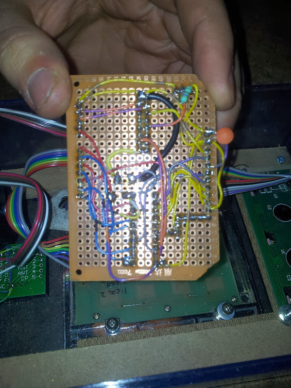
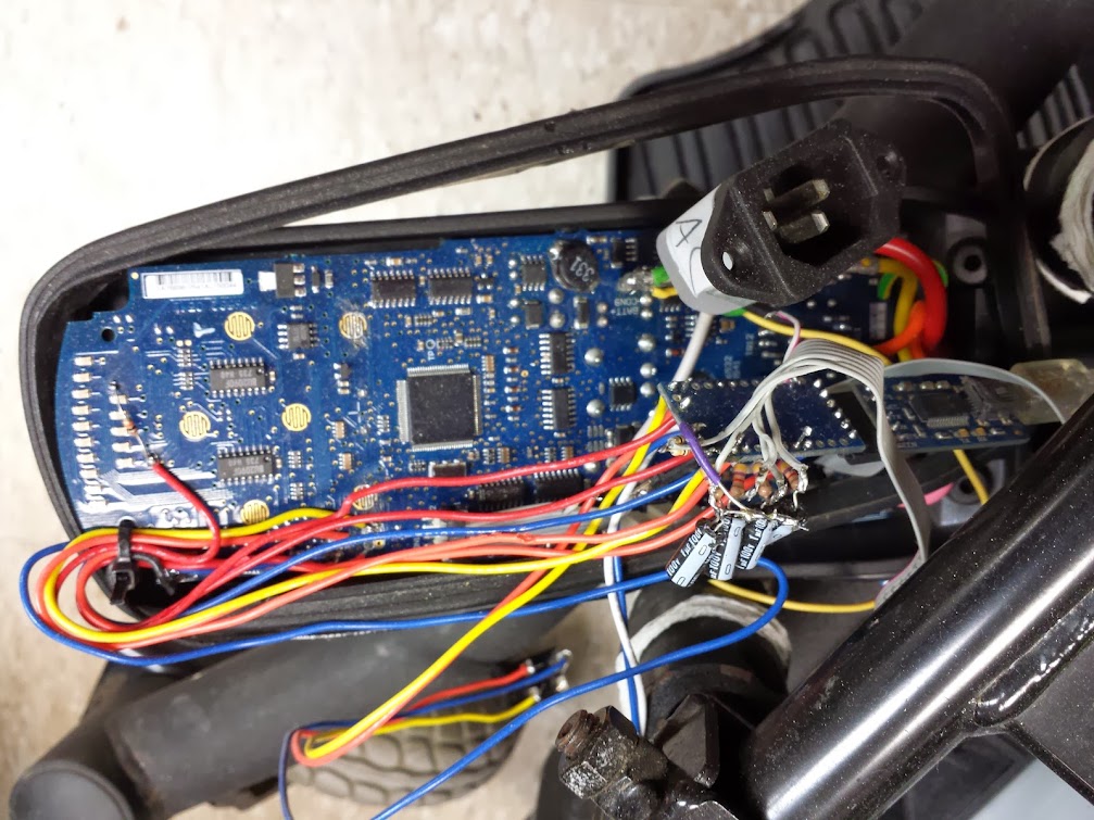
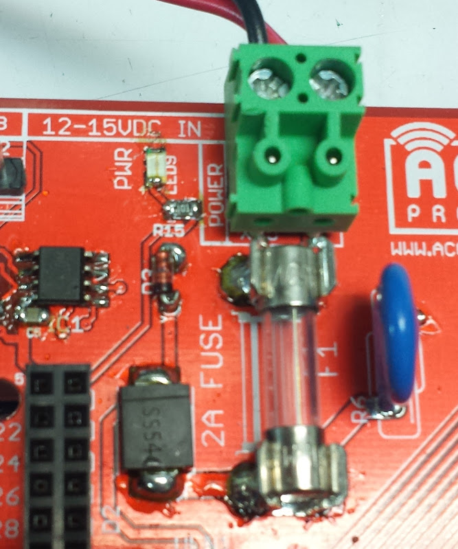
This is the power section for protecting the rest of the board from a flaky power supply

Here is our switching regulator, that big resistor is the current sense one of a very small rating

This is the relay driving circuit, it goes through a buffer/driver and has individual LEDs

So, admittedly this is heavy on pictures and light on explanation.  Most of the explanation will be in the article that describes the code.  At some point I’ll tie all these articles together.


Wiegand keypad

June 30, 2016

So far with the OpenAccess system I’ve talked about the rs485 terminals I tried to use, a clever low pin count display and keypad, the final display and keypad controller I built, and the ability to log to a dot matrix printer.  Now I’ll talk about another I/O system that I tried but didn’t end up going with: a fully wiegand keypad and rfid reader.

I don’t think I’ve discussed wiegand here before.  This protocol is like a cross between rs232 and rs485, but originated with magstripe readers.  I’m going to spin you a tale that may not be entirely accurate, but I’ll tell it in such a way that it could be.  Back in the day when magstripe ID cards were starting to be used for everything there would be readers on tons of doors in every building of an entire campus.  This could be a government facility, a college, or just a security-conscious private company.  Having lots of distributed computers doing local processing or encryption and all sending data back along the same tcp/ip based network is how we do things now.  There was a time that paying people to run lots of wire was cheaper than put in micro computers everywhere.  In these dark times the magstripe readers would be at the end of a long cable, untwisted because that too cost money.  We have been sending high voltage (the spec doesn’t specify voltage, but I’ve seen as high as 30V peak-to-peak) rs232 from building to building for a while, but with no control lines and no communication back to ask for a re-transmit there needed to be a way to get the data transferred correctly the first time and do it cheaply: wiegand was born.

Wiegand is digitally signaled by sending the ‘ones’ down one line and the ‘zeroes’ down another.  This is effectively like having a deferentially signaled line, except the timings are such that both lines are low between bits.  If you relax your timings a bit you can get away with using just one of the wires (I don’t know anyone else who does that… GM) but it’s not generally good practice.  There may be no way to ask for a retransmit from the microprocessor, but you can certainly ask the user.  My wiegand readers have LED and buzzer outputs that can be driven by the controller.  I said this was born of magstripe cards, lots of magstripe readers put this out natively, or they do inside between some controller chips.  In order to keep up with the changing security concerns facilities went to rfid cards, but due to rampant and perpetual cheapness they kept the same backend hardware, software, wire… and just slapped these readers on the front which spit out the same codes as the magstripe ones.  I may put up some documentation I have about probing a facility in transition later.

Now that we know what wiegand is (and hopefully you hate it like I do) let’s talk card length.  The cards I use are 125khz, unencrypted, and have a 26bit code in them.  There are ones up to 34 or 37 bits, some that use different frequencies, encryption, and some that have dual frequencies for compatibility.  There are no cards as short as 4 bits, that would be crazy, you could only have 2^4 combinations.  What would you possibly do with 1/16 possible combinations.  Oh, right, the keypad has 12 positions.  So, in order to read this keypad you have to poll for wiegand data and if you have accumulated 4 bits of data and after a short while are accumulating no more then you have a button press.  Now, if you don’t know you’re looking for button presses differently you may press 6 buttons and find yourself having read a card that doesn’t look like any card you’ve seen before.  Could the designers of this keypad put in 16 full 26 bit streams that correspond to key presses? yes.  Did they? No. Is this a good design practice? You decide.  If you want to be all exact about it you can start a timer when you get the first interrupt and figure out if there’s an unusual pause between the fourth and fifth bit which would indicate someone pressing buttons, you could also just poll constantly and assume that the buffer will be exactly 26 bits or 4 bits when you read it because of how fast you poll.  I split the difference, if the buffer has more than 25 bits in it I assume it has a card, remove 26 bits, act on it, and check again.  Else if the buffer has exactly 4 bits I assume the buffer has a button in it and read that.  I make no provision for polling the buffer while the interrupts are filling it up and that’s not been a problem for me yet.

There’s how to read the wiegand keypad.  If you ever have trouble feel free to throw it away and get a real protocol before calling me.  Or call me, I’m not usually busy.


the keypad test code is here

Arduino keypad and display

June 29, 2016

“This project was originally started as part of the i3 Detroit OpenAccess control system for RFID entry.  I promise I’ll write an entry on that soon, but I’ve got to shake down all the bugs first.”  That was two and a half years ago.  I’m going to do a write up of all the aspects of the system I designed even though I have no intention in actually implementing this system.  The reasons I have for not using it are basically: I won’t be the only person responsible for repairs/debugging, I won’t implement any more features I don’t think are useful, no one has stepped up to learn about it.  The system it’s replacing is an off-the-shelf rfid mag-lock with keypad and while that is lacking a lot of features that would be helpful I am not moved to change anything because the benefit of features vs. the cost on my time is not worth it.

The first aspect of this system is the front panel controller.  My re-implementation of the OpenAccess system had to start with adding the ability to enter PINs.  Now, there are plenty of other systems that hackerspaces use or have built but a minority of them use PINs, it just seems that they either choose a more interesting method of second factor in their identification or forgo it entirely as being un-needed.  Considering the physical part of the security is usually the weakest link in the system most people have decided that the brick next to the window makes a PIN to go along with the key sorta pointless.

old schematic, not using i2c for the final design (and am setting contrast locally)

Since I rewrote everything from the ground up I got to choose a control panel for the outside.  Originally I wanted to use the rs485 control panels but talking to them ended up being cumbersome and the more I used them the more I hated rs485 (at least use rs422, it’s full duplex).  This control box has 12 volt power, ground, wiegand signals for the rfid reader (the buffered inputs are on the OpenAccess main board) a single ds1822 temperature sensor, rx and tx pins to the atmega I’m using, and (according to my schematic) the contrast pin for the lcd.  I can see from my code for driving this display that I am controlling the contrast locally (actually, for outdoor use a VFD would be much better in michigan winters and as everyone knows is sunlight visible).  I am not reading the temperature locally, although I have the spare pins to do that.  You can see for the RFID reader I put an orange LED and a western electric warble buzzer on the output pin of the rfid reader.

Old processor

Adapter!

This code started out as an i2c display and keypad that used an attiny.  I thought that if I used someone else’s code I could avoid having to debug it.  WRONG! Let’s start with this: if you ever try to use i2c over a cable, just don’t.  Inter-integrated circuit communication should be done on a single board.  If you have to go off board use SPI or UART.  My experience with that i2c controller wasn’t great.  I think I might have been running up against memory restrictions on the attiny2313, but considering a pro mini from china is about as cheap as sourcing a single attiny chip here…. I replaced it.  My code for the display uses serial, good old fashioned reliable serial that takes no special tools to debug or talk to.

The code I have works like this:

  • read for serial commands and do any of them
  • if a key was pressed, return it over serial (no line breaks)

That’s it.  The commands are for brightness, contrast, display, and display line.  The display command works from the last cursor position and the display line command rewrites the whole line.  That is exactly how simple this code is.  The contrast and brightness are done with PWM from the arduino pro mini, I use a keypad library and serial command library (specifically modified for the 328 as opposed to the 2560 which I will cover in a later post).  I fully support the modularization of your software, this extends to the modularization of your hardware.  I could run a thicker cable and have all the keypad and lcd pins run back to the main microcontroller, I could even use local chips to multiplex those pins, but having a second brain at the other end able to take human-readable commands just made it so much easier.

New processor

Code is here.

Pictures and schematics are here.

Wheelchair robot

June 29, 2016

Back in college (yeah, those were the days) I was in a hackathon with a couple other guys.  What we decided to do was to build a robot platform out of a wheelchair.  While researching for this article I found out that we are not the only ones to do that with this style wheelchair, but I think we implement the most functionality.

We chose to interface with the existing controller since it already does what we want.  Power was not an issue as you can see the battery voltage is brought right to the controller and helpfully labeled.  The inputs and outputs were:

  • in: power state (using an analog pin and LED)
  • in: power switch (manual control passed through our code)
  • in: speed up switch (manual control passed through our code)
  • in: speed down switch (manual control passed through our code)
  • out: power relay (controls the power switch on the pcb)
  • out: speed up (controls the speed up switch on the pcb)
  • out: speed down (controls the speed down switch on the pcb)
  • out: speed/speed2 (sets the position of the virtual analog stick)
  • out: turn/turn2 (sets the position of the virtual analog stick)

In addition to these we also used the usb-serial converter on the serial lines to communicate with the laptop.  Through incredible self restraint we didn’t implement the horn functionality.

Here is our modified controller.  You can see the joystick connection is modular so we could probe the lines in circuit before connecting our controller to them.  That proved absolutely essential because this controller is a little smarter than you might imagine.  The joystick has 2 separate potentiometers for each axis which we drive with identically controlled pins on the arduino pro mini.  The controller also throws an error when the virtual joystick goes too far out of the range of the mechanical joystick.  we have capped these pwm outputs using a helpful map function:

speedOut = map(speedVar, 0, 1023, 50, 210);
analogWrite(SPEED_OUT, speedOut);
analogWrite(SPEED_OUT2, speedOut);
turnOut = map(turnVar, 0, 1023, 50, 210);
analogWrite(TURN_OUT, turnOut);
analogWrite(TURN_OUT2, turnOut);

This allows us to work in 1024 increments of turn and speed while knowing we won’t trip the internal protections against an unplugged or shorted joystick.

The code written here is non-blocking and runs in a continuous loop.  It checks to see if any switch is pressed and does the corresponding command if needed.  It then checks to see if there are any serial commands that need executing (I’ve used this serialcommand library before).  Once it executes any needed commands it sets the virtual joystick based on the internal variables stored for the position.  It checks to see if it has been more than 3000 loops since the last command given, and if so it re-centers the joystick (a crashed python program sent it driving off since we no longer had a spring return joystick).  The commands it takes are :

  • TURN [0-1023]
  • SPEED [0-1023]
  • SPEEDLEVEL [-1,1]
  • POWER [0,1]

Turn and speed set the joystick position (512 is center), speed level pushes the relevant up or down speed button (which just scales the joystick, increasing or decreasing the max speed), and power turns on or off the wheelchair controller (not our controller).  Since these commands just push buttons it is not possible to know if you are at the max or minimum speed (we did not read any more LEDs, but you could).  We did, however, implement the power LED.  When you want to turn on the controller it checks to see if it is already on and then sets the joystick to center, presses and holds the button for 100ms, then releases the button.  This is also part of a safety interlock to keep the wheelchair form just taking off when turned on.

The power connector passes 12V for charging and is labeled as such. I didn’t do that part, I promise.

The power connector passes 12V for charging and is labeled as such.  I didn’t do that part, I promise.

The next bit of software I didn’t write.  We interfaced this robot with a laptop and a kinect for doing depth mapping.  You can see that code here and your interpretation is about as good as mine, but I will try.  I will say that this code is sending speed, turn, and power commands as one even though I am processing them individually.  The speed up and speed down are not used (we used the manual switches in the robot).  The logic in the python code looks at a center depth, a left and right side.  If the robot is clear to move forward it does, else it goes left, else it goes right, else it backs up.  The behavior is very simple and the movements around our oval-shaped hallway were interesting.  There’s enough lash and randomness in the mechanics of the wheelchair to make sure it never gets stuck even without more complex self-correcting code.

That’s it.  How to make a wheelchair based robotics platform and how to interface that low-level arduino control to a python script.

pictures are here.

code is here (forked in case he wants to bring it down)

2.4Ghz analog camera scanner

June 29, 2016

This story has a part ‘back in the day’ and a part just a couple months ago.  Let’s start with the most recent part.  I decided that I want cameras around my house.  I didn’t say in my house, I said around my house.  I would like to be able to see my front yard, back yard, driveway, and maybe even down the street a bit.  I want cameras inside, but this is absolutely not the way to do it.  I came by a number of analog cameras with 2.4ghz transmitters, but the receiver I had used analog tuning.  I never worked out whether it would pick up all 4 channels of camera (there are 4 in the standard I’m familiar with) or just fine tune on 1 but either way I decided that using analog tuning is harder than it needed to be.  I went on ebay and picked up a 4 channel receiver with a switch going between channels.  With that I got all 4 of my cameras on different channels and able to be picked up by the receiver.  In the process I found a camera outside that picked up my hackerspace (probably by the landlord based on where it was and was pointed).  Now, even if I didn’t already not want these cameras inside… I would like to think this would have done it.

Before I go on with this hack (which is, as always, half finished) let me bring you back to my inspiration for this one.  If you look up the origination of the term ‘wardriving‘ which is what I grew up doing (driving around picking up people’s wireless networks and using/breaking into them) you will find ‘wardialing‘ which is basically robo-calling for modems.  This was popularized (if not originated) by the movie WarGames because before Matthew Broderick was doing his best Gene Wilder impression, he was impressing girls with his computer skills.  This is a different kind of automated scanning attack, the one I’m thinking of is ‘warspying‘.  Eleven (!) years ago Systm launched and had an episode with a howto for building a handheld unit for detecting and displaying unencrypted wireless cameras.  I wanted to use that technique to drive this switch from a raspberry pi (or any other computer with gpio).  Where they used a small pile of discrete I/O to accomplish a dedicated scanner I used a simple demultiplexer, a 74155, to control 1 of 4 lines with 2 GPIO.  Since I only need one line grounded at a time I can use this technique to save pins.

You can see from this switch diagram (or the description in the Systm video) that the switch has 6 pins and 4 positions.  If you ground the two center pins then you ensure that one of the outer 4 pins is grounded in each switch position.  Rather clever for what would otherwise have been a more complicated mechanism. That being said, this doesn’t scale very well.

I really wanted to replace the whole board here, or at least make the unpopulated stuff work but that just never happened for me.  For anyone else with one of these modules, now you know what’s inside so you’re prepared before you go tearing it apart.

Now you can see how I made a camera receiver interface with a raspberry pi.  If you send 00 out two pins you get channel 0 of video, if you send 01 you get channel 1, same for 10 and 11.  Until this actually gets used with GPIO I have set up a 2×3 jumper block with power down one side, ground down the other, and the two data lines in the middle so they can be pulled high or low.  There is no ‘off’ since that wouldn’t matter, the video capture card is connected straight to this module and there is no need to switch it out for anything else.  If you needed to it could be done with a 4051 analog mux though.

pictures related to this project are here.

TTL POV globe redesign (part 1)

June 28, 2016

Back in college I built a POV globe.  I was really not happy with it, mostly because it’s something I felt could be done with discrete hardware more easily.  The first part to getting the POV globe in chips is to work out how to store the lines and retrieve them.

The big plan includes using a bigger chip with bank switching for animations and maybe even higher bank switching for going between animations.  This means that we need X address lines for 2^X lines, Y address lines for 2^Y frames, and Z addresses for 2^Z animations.  Eventually I would like to have a dynamic clock divider so we can have a variable speed motor and still scale the line frequency to keep the image all displayed in one revolution.  For now I have put together a clock out of a 555 timer, and decoders for the 28C64 EEPROM made from 74LS161 chips.  The EEPROM was programmed using the TL866 programmer to a sequential pattern as an example.  You can see that this chunk of the circuit iterates through the addresses and the outputs are tied to LEDs.

<video showing reset circuit>

<video showing addresses counting up>

<video showing changing the clock speed changing (blink pattern in the chip)>

Next time maybe I’ll have a dynamic clock divider circuit.

here is the code.


Design a site like this with WordPress.com
Get started