Archive for the ‘projects’ Category

Siemens PLCD5583 arduino library/demo

June 26, 2013

OK, now I pulled one of these off the front of a rack mount server (dell, I think) and it’s really a pretty old design.  This display uses an 8-bit data bus for the character to display, and a 4 bit address bus to pick the digit to display it on. They also have a plethora of other features: individually flashing characters, blinking the display, brightness control, lamp test, and clear.  First: the flashing characters.  You can set a register for each character to set that character as either flashable or not, and set the characters that can flash to flashing or not.  There is a second bit that can be set to blink all the characters at the same time.  Next we have the lamp test function: this one sets the character to all on, and all the segments are on to see if any of them are out.  The clear function is pretty obvious, the brightness control has three bits of control from off to full brightness.  The code I have here on github is not a library (yet) mostly because I think I should use shift registers to minimize the pin count.

“Computer” speakers

June 26, 2013

This is a very old one, maybe I’ll update with an approximate date later, but it has to be before 2006.  So, I’m a smart ass, and so are my friends, for the most part.  We had a pair of computers that were close to absolutely useless, some old HP pavilion compact towers.

 They were absolute crap, no good for anything, but for some reason we got the crazy idea to turn them into a set of speakers.  So we did just that.  First we stripped the cases of all the computer bits.  Then we stripped the cases of all plastic bits. Then we stripped the cases of all internal riveted-in metal bits.

We turned these into metal rectangular prisms.  Once we had the cases prepped we needed a donor amp and speakers.  The amp was sourced from an old pair of speakers that came with a Pentium 4 era eMachine desktop, the speakers were surplus paper cone car speakers.  No, we didn’t match the impedance, yes they were probably both 8 ohms.

Now we have speakers whose magnets can seriously affect CRT monitors and cases that fit them pretty well, now how do we put it all together? Duct Tape!

That’s black duct tape, this adventure pre-dates gorilla tape

Here they are assembled, they worked wonderfully until we gave them away to a friend.


The rest of the photos are here.


simple VGA splitter

June 26, 2013

Here’s a dead simple hack that anyone with a soldering iron and some reasonable skills can do. Take a piece of radioshack protoboard, 4 board mount vga ports (salvaged is easiest), and some solid core 80-pin IDE cable and build one of these.  They do degrade (dim) the signal by not being as bright since the 75 ohm termination is broken by simply wiring them in parallel, but this is no worse than buying a splitter from monoprice.  My use case was wanting one monitor at the main desktop, one at the workbench, and one at the couch but not needing the images to be different since I can only be in one place at a time (for now).  This 4-way female connection allows one input and 3 outputs using conventional male-to-male vga cables (none of this male-to-female KVM cable stuff).  I tried to do this only populating the data pins to one monitor and just duplicating the RGBHV to the others, but for some reason that didn’t work.

Simple ethernet link tester

June 26, 2013

I have an ethernet cable tester, it takes a 9v battery, has some 4000 series logic and some LEDs and blinks them based on the integrity of the cable.  This new tester takes some nearly useless old technology and makes a fantastically simple device that simply reports the state of the ethernet link to actual running network equipment.  I will state flat out that I got this idea from this instructables article and that I added no content to it whatsoever.  I am posting about it because I want more people to know about how easily this hack can be done, and how useful it is.  To start off with we have an 8p8c to DA15 network adapter.  Yes, I am going to be pedantic about connector naming, see here for the D-subminiature wiki article, and here for the RJ45 vs 8p8c debacle.  This is commonly known as an AAUI (or AUI) to RJ45 adapter, meant for connecting two ethernet connections that are not electrically identical.  The hack is truly simple, just hook up ground and power (supposed to be 12v, we’re running it at 9v) and away we go.  There is also a momentary push button so power is normally off, but that’s optional.

 The two ethernet converters I modified had different indicator lights, the Link light on each light up when a valid device is at the other end, and one even had an Rx light that glows when the network sends broadcast messages.  I have no idea how such little hardware can determine a valid link, but I assume there is a hardware level detection done independent of any actual data transfer over the cables.  The whole gallery is here.

Cordless headphones revival

June 26, 2013

So, who here hates bluetooth audio? Now who knows what it is? Good, all the same hands stayed up.  I have an alternative to this crappy option: go old school!

Ok, now I picked up these headphones some time in the past, probably at a garage sale.  They are, specifically, Optimus 33-1145 900 Mhz headphones, FCC ID: CLV-A900T.   Originally these headphones had a Ni-Cd pack that allowed them to be re-charged form the base station, it was long dead.  So, to get these operational I need a power adapter, and a new battery for the headset.  Let’s start with problem 2 first, the battery.  The battery supplied 3 volts, was triangular in shape, and had a charger port on the side of the headphones where it could plug into the base.  I really wanted a cheap solution, so I took the best of my 2xAA battery holders at the time (from an old AV receiver IIRC) and glued it right on the outside.  I removed the charging port and re-located the power LED that the battery covered up now.

the on/charge switch is now the on/off switch

Good, now the headset is converted to replaceable batteries (or, you know rechargeable AAs or whatnot) let’s look at the base station.

with mods applied

Here is the back, it has a DC power jack originally spec’d for 18v, a 3.5mm headphone jack for charging the original battery, a volume control, audio in in a less than useful format for my purposes, and a frequency fine tuning knob.  Now let’s look inside and see what I did.

So, right away two things should stick out: that yellow wire bypassing a voltage regulator and that charging jack doesn’t look stock.  The charging jack was removed, flipped over, and glued back down to be a 3.5mm audio in port (it’s wired in parallel with the other audio jacks on the bottom [with shielded cable even!]).  The regulator was there because the original power brick was apparently very unstable and needed to be cleaned up for audio use.  I did this so long ago I can’t remember why I spec’d the new power supply at 16v, but I trust myself because it’s working.  So now we have a working headphone set, cool! but what other features do we want?

Another headphone jack of course! I could have done this right and used a switched jack, but that wouldn’t allow me to tether a friend to me so we could both listen together.  My motivation for this was mainly that now I can play music (I mainly listen to audio books, but I’m strange like that), walk around the house, and when I get to a place with a set of powered speakers I can settle in, plug the headphones into the speakers and keep listening rather than have to queue up the track on whatever computer was nearby and hooked up to those speakers.  So there you go, replaced a toasted voltage regulator, replaced rechargeable batteries with replaceable, and even added a new feature.  I think this one worked out pretty well.  Full album is here.

Replacement power supply build

June 20, 2013

I say build, it’s more a mod.  A long ,long time ago in a college town far away I helped a friend move into his frat house.  After I did this one of the housemates gave me an old monitor and power supply simply because he didn’t need it.  I gladly accepted it, but when I checked to make sure it was the right power adapter I noted it was a 12v 1a one, the display called for a 16v 3a one.  Now, I don’t know exactly the audience I have (yes I do, it’s web spiders) but I’ll tell you right now: there’s no way that will work.  I mentioned this at the time, but was assured that that was the adapter he always used for it (no it wasn’t).  My persistence at wanting this thing to work may seem misguided, but here’s the thing: this isn’t a computer monitor, it’s a TV.  Now I know what you’re thinking  that’s worse right? Right.  But in this case I don’t want better, I want more.  This TV (Phillips 20pf5120/28) has a cable tuner (useless), a composite input (expected), an s-video input (expected, but appreciated), a component input (cool! my first component input), and a dvi input (what?).  The DVI input can only do a resolution of 640×480 (and only digital), but it’s a 20″ 4×3 LCD TV, what more can you expect?  Let’s look at the specs for a new power adapter, shall we? 16v DC: that’s not too hard, if it were 12 or lower you could use a linear reg on a computer power supply to get that, but it’s not too bad.  3a: here we have a problem; that much current usually warrants the power supply to be inside the device it’s powering so those are a bit hard to come by, or at least they were.  I say that because we are now in the era of scrap laptops.  Yes, that’s right, laptop computers are being thrown out left and right for all manner of faults: broken screen, dead battery, won’t boot, broken power adapter (more on this later).  The thing about laptops is that they take a lot of power, sometimes upwards of 4.5a.  The problem now becomes the voltage.  Laptops generally run off of somewhere between 18.5v and 20v to charge their lithium ion batteries.  Let’s see what the junk drawer has to offer.

image taken post mod

We have a nice 19v 3.25a laptop power supply: perfect! Ok, there’s still that voltage problem; there are two ways to tackle this: a switching regulator, or a linear regulator. The switching regulator is a much more efficient design, but requires parts I did not have on hand.  The linear regulators could not pass enough current (1.5a max) but that’s ok, we’ll just put 2 of them in parallel to get that extra current through.

The design of the linear regulator circuit is simple, we use a fixed voltage linear regulator and a voltage divider made out of two specially chosen resistors to set the voltage to whatever we want.  For this one I just pulled out my phone and used electrodroid, but the calculation is simple to do if you want.  The heatsinks are mandatory since I’m running these regulators at the ragged edge of their tolerances.  There you go, a 16v 3a dc power supply that will give you second degree burns if you handle it wrong.

I swear I build these things better when they aren’t just going to be used by me

DIY Power Supply

June 15, 2013

This was one of those projects I knew I had all the parts for and it just took being bored one night to decide to actually do it.  I decided I wanted to make my own power supply, not just a modified computer power supply, but entirely from scratch.  This may not have been the best idea since it’s entirely based on linear regulators (I did put heatsinks on them, but no ventilation).  Anyways, here it is:

I should emphasize that I purchased none of the parts to build this project myself, they were all either donated, salvaged, or found.

The base circuit for this I got from here and I modified it slightly to suit my needs.  I decided that I wanted 5, 12, 3.3, and a variable voltage output (at this point I realize I could have done all of this with a computer power supply, but too bad!).  The second place I got inspiration was this EEVblog post, I decided I needed some more equipment and built some.  Now, some design decisions based on parts on hand.

First, it only goes up to about 14vDC.  it was the best transformer I had on hand at the time (although before rectification I read it as about 12vAC, I have no idea why it’s higher once rectified).

Second, I have fine and coarse knobs since I couldn’t find my 10 turn pots (they had ball bearing based planetary gears).

Third, I opted not to have power cut switches for the regulator inputs (space concerns) but I do have output switches. I originally wanted to cut power to the regulators because they would just be dissipating heat otherwise.

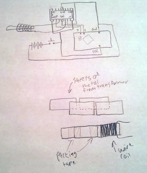
<where my schematic would be if I bothered to make one>

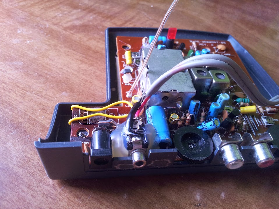
OK, now that that is out of the way I can explain a bit of my design process.  I took the base circuit from Raijuu.net and modified it to suit my needs.  I didn’t put in a fuse since I didn’t have one on hand (well, I didn’t have a panel mount holder).  The power connector, rectifier, and power switch are from a computer power supply, the transformer came out of some old piece of equipment, probably a radio, or amp, or something (it was in my ‘transformers drawer’), the large filter capacitor is of unknown salvaged origin.

As you can probably already see the entire thing is put together with computer power supply wiring and ethernet cable (how else would you know I built it?).

Up to this stage we have a 14vdDC power supply with a switch, now let’s get some useful voltages.  The 5v and 12v legs of the power supply were built exactly according to the Raijuu.net schematic, except I calculated the resistor for 25mA (1.2v red LED) and I put a switch between the output and the LED.  The 3.3v leg was basically the same exact circuit as the Raijuu.net variable leg except with r1 and r2 fixed.

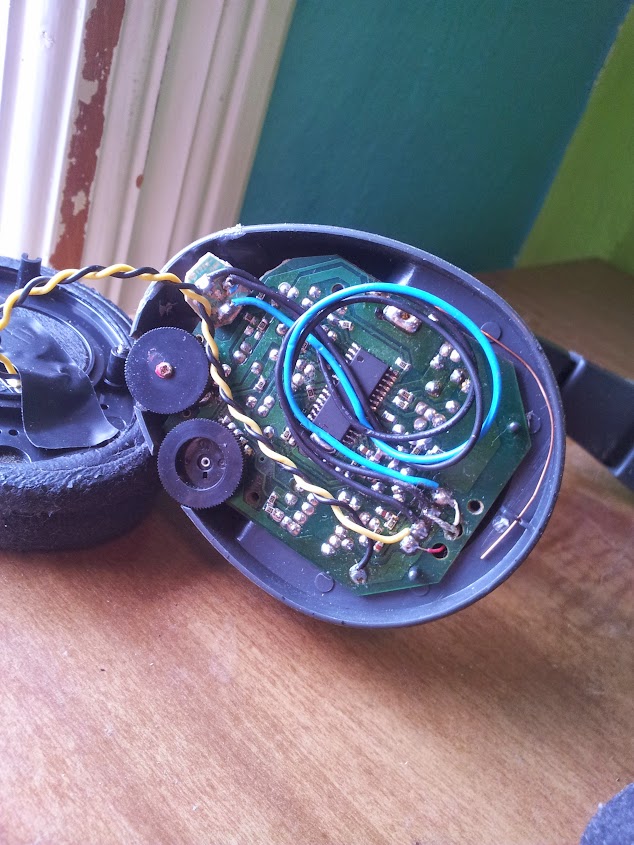
The variable portion of this build was the same as the 3.3v leg, I had some pots lying around from an old equalizer whose transformer blew and figured a 1k and 5k in series would constitute decent fine and coarse pots.  I called that a 6k r2 and set r1 toso the max voltage was just below the point where the lm317 started freaking out about not enough input voltage.

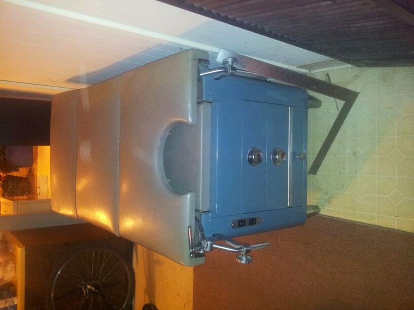
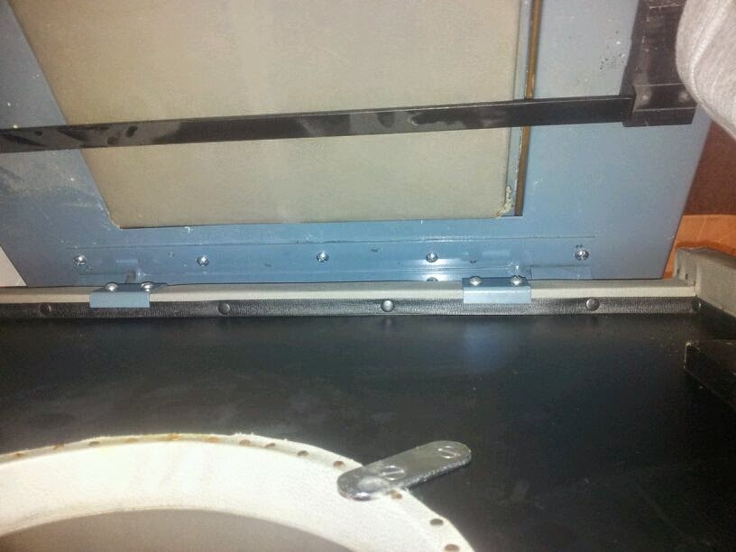
That basically covers the entire circuit, the enclosure is a standard radio shack project box I got from a friend’s box of un-finished projects (I think), the screws for this did not come with the box, I assume the originals were pan head and these are not.

The banana jacks came off an old electronic educational board (the sort of thing that exists so you can build circuits with just banana cables).

The project was compressed onto this proto board as much as possible, but the LEDs and resistors were done hanging.


This has been a simple overview of my power supply (I intended on posting this a long long time ago, but I got sidetracked thinking I was going to make a schematic).  

Arduino to dot matrix printer

June 15, 2013

If you can’t tell I’m dumping a huge backlog of things I’ve wanted to document for a long time, don’t think I can keep up this post rate for long.  Here’s a really easy one: talking to a parallel port based dot matrix printer.  To be honest this can probably be used to talk to any parallel port device (especially printers), but we’ve tested it on a dot-matrix printer.  We’ll start with the basics: what is a parallel port? A parallel port is a port popular on computers for the past couple decades that allows you to set an entire byte of data on the pins simultaneously and a bunch of control lines to exchange commands between devices.  The best documentation I have ever found for the port is here, but the important pins are data[0-7], strobe, busy, and ack (although that last one turned out to not be used on this particular printer).

I built a cable that accommodated all the pins even though I knew we weren’t going to use them.  The thing about “modern” serial protocols like RS232 or SPI is that they go one bit at a time, and this method does whole bytes at a time.  The way we achieve this is by using what are called bit masks.  Bit masks are where you essentially take an entire byte and do an bitwise AND with a mask to only leave whatever bits on and also on in the mask.  The way we use bitmasks is to mask off all but one bit at a time so we know what value to set each bit on the parallel port to.  Once we have one byte on the port we simply have to toggle the strobe pin to let the printer know when to read the byte.  After the printer has started reading the byte we keep checking the busy pin to see if the printer is done yet.  Once the printer is done reading the byte you are free to set up the next one.  The printer is SUPPOSED to flip the ack line when it’s done, but this one didn’t.

The next important thing is to understand what the non-printable characters in the ASCII table are.  The ASCII table is the definitions for all the bytes you can send down a standard ASCII compatible serial or parallel port.  Most people focus on the printable characters because they can be seen, but when you’re talking to physical hardware the use of in-band signaling  is important.  The one non-printable character I will never forget is 7; bell.  This character is supposed to tell the terminal to emit an audible sound, but frequently if you throw it at things like IRC, printers, or other things that are not serial terminals they try to implement the entire ASCII table including the non printable characters, which means they ding… every time the screen is rendered.  This printer did not have a bell, unfortunately.  The important characters are Carriage Return and Line Feed.  These go back to the typewriter days where a CR puts the carriage at the beginning of the line and the LF moves the paper up one line.  These are frequently used these days as signers of the end of a line (as they were when they actually incremented the paper) but sometimes they only use one or the other which saves one byte of space, but doesn’t make much sense from a technical standpoint (not that anyone really uses a CR without a LF these days).  This printer was fairly smart; it only moved the carriage as far as it has to go to print the characters on that line (rather than moving all the way across the paper), but it wouldn’t move at all until the entire line truncated in a CR LF was sent.

This was implemented as an output for the future i3 Detroit rfid entry system, but can really be used anywhere 10 IO are free (or, if you want to be a little ironic, use a 74595 for the data).  The entire entry on that system can be found here, but the code for the serial to printer test is here.

Magnetic card emulator

June 15, 2013

This is a project that developed more out of curiosity and a bit of mischief, but developed into a useful device.  Let’s start with what a magnetic swipe card is used for.  In the united states we use magstripe cards for student IDs, credit cards, drivers’ licences, pretty much anything that requires us to quickly and easily authenticate ourselves.  I understand that the rest of the world has moved on to RFID, QR codes on phone screens, NFC, and all other sorts of authentication methods, but this is the united states, and we’re big.  I don’t get how that means we’re perpetually behind the technology curve, but ok.  I have heard arguments that “of course our internet is crappy and expensive compared to the netherlands and south korea, we had it first, it takes a lot of money to upgrade these systems”.  Shouldn’t profit scale linearly with population? actually if you count start up cost, a larger population should amortize the start up cost to be lower per capita so the ISPs and banks in this country make even more per person than in smaller countries.  I guess having one or two major companies doesn’t really breed steep competition (hi google, keep it up!).  This card standard has been around a while, it uses three distinct stripes that can hold data in well defined ways as seen in the ISO standards mentioned here.

These cards communicate by having opposingly magnetized areas in the stripe that induce a current in an electromagnet when they change polarity.  One way to simulate one of these cards is to simply create a chunk of magnetized card that has the same transitions, but the easier and more software definable way is to use an electromagnet to simulate these transitions.  Now, having 3 distinct electromagnets makes it hard to simulate a multi track card as you have to feed different magnetic fields to each electromagnet.  This would make simulating a drivers’ licence difficult because they use multiple tracks to store data.  Now, if you only need to simulate one track then you can do what I did, which is to create a big honking electromagnet and spam all electromagnets simultaneously.  This method is only useful for the least secure and cheapest of all magstripe cards. Guess which ones My school uses?

The seed idea for this came from people recording and playing back these signals from an ipod.  This method looked cool, but I really wanted to be able to define the card ID on the fly.  This brought me to the arduino card emulator, but that code was a bit off from what I needed it to do.  After a friend re-worked the code we have this.  The place with all the zeroes is where you put the card number as read by your friendly track 2 ps/2 keyboard pass through card reader.  Oh,you don’t have one? check out this sourceforge project.  This emulator only uses an h-bridge, an arduino, a coil of wire (I unwound a transformer for some), and a sheet of metal.  The metal I chose is a small pile of sheets from the transformer glued/taped together.  I used that metal because I knew it wouldn’t hold a magnetic field and would transmit the field change fairly well.

I suppose this is a fairly short post, mainly because it’s a fairly straightforward project.  The arduino pro mini used in this version has a power LED, it dims as the h-bridge draws current from the batteries and browns them out.  This unintended feature is nice to see it actually “swiping” the card.

The non-malicious use of this device involved the fact that my school gives us ID cards that deteriorate at a surprising rate and charges ~$10-$30 for a replacement, since they only use track 2, I use this.

UPDATE: I have been asked for specifics, I used a 5V arduino pro mini and fed the ~6v directly into the VCC pin of the pro mini.  Taking a look at the schematic on sparkfun you can see that the RAW pin is the input for raw voltage to be regulated down to you VCC voltage, I’m running a bit higher than the arduino is spec’d for, but with some old alkaline batteries you usually don’t get over 5.5v (which is the top end of the spec for the 328).  I assume you can use the 3.3v one, although I haven’t tested the code to make sure the timings still work right.  If you are in doubt you should check the integrity of your emulated card by making sure it shows up properly in the same ps/2 pass through reader you used to get the number in the first place. I? have no specifics on the coil size, but I think I used about a meter or two of wire (I could be wrong).  If you really want to be specific you can measure the resistance of the coil and the supply voltage and use V=IR to check your current draw and decide whether or not it’s too much for your batteries.

BOM (bill of materials):

arduino pro min (5v 16mhz knockoff from ebay)

momentary button

L293D (or SN754410)

magnet wire (salvaged from a transformer)

sheet(s) of metal (salvaged from a transformer)

wire

electrical tape

hot glue

Schematic:

I would refer you to the datasheet of the H-bridge for further information, but if you still don’t understand after reading that I can probably help.

Gynecology table repair

June 15, 2013

I didn’t break this one.  Ok, I just felt like I’d open with that, I don’t get to say that too often.  This also differs from my normal electronics hacking, but I really have this motto: “if someone else can do it, I certainly must be able to” and an addendum: “if no one else can do it, it’s only because they aren’t as good at it as me”.  That’s mostly sarcastic, but it is a bit more honest than “if at first you don’t succeed…”.


This time I’m repairing a gynecology table.  I’ll let that sink in for a minute.  Ok?  Good, let’s move on to the story.  This table was purchased by a very good friend’s uncle for use at his tattoo parlor.  I believe the intended use was/is as a piercing table, and that there was a story that went along with this table that sorta motivated us to get it fixed.  As you can see, this is a vintage table, so repairing it was even more interesting and important.  The problem with it was that when it was moved someone decided to lift it by the tilting part that you see on the right and broke some welds.  I think the original construction method was a series of holes in one sheet of metal, and pegs sticking out of the other so welds could be made along the center of the hinge rather than the edge.

Onto the fix! The easy way to fix this was to drill out the pegs and replace them with nuts and bolts.  Luckily the hinge was bolted onto the seat so all we had to do was unbolt that to take it somewhere else to work on it.  A quick run to Home Depot got us the right parts (and locktite of course), but where could we get a drill? Oh, there’s a metal shop in the basement of a tattoo parlor.  Yup.  Drill press and all.  That was easy.  Some lubricating oil later we had cleanly drilled holes, brought it back and installed it, very easy.

I don’t know what model this was since I’m bad at pictures, but I know that of the things it came with it’s latest patent date is 1943.  So, this has been a tutorial on how to repair a broken post-1943 Hamilton brand gynecology table.  This was the way I spent my last day visiting in Seattle, and it was probably the best way I can think to have spent it.  Full set of pictures here.


Design a site like this with WordPress.com
Get started