Archive for the ‘projects’ Category

Door Iris

June 28, 2016

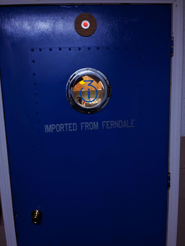
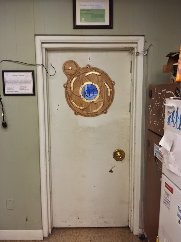
At i3Detroit we had a door (as seen it the scrolling, scaling web 2.0 bliss that is i3’s main page [just go to the wiki for important stuff]) that frequently got opened into groups of people standing by the front door.  The groups stand there because despite this door always having existed someone decided that a good bottleneck for people is right there, in the way.  Other hackerspaces have paperwork filled out elsewhere in their space, places where you can sit down even, but not us.  I chose not to solve the problem of people congregating because it didn’t seem interesting.  Instead the problem to be solved was that the door was a bit too opaque.  We could, of course, put a window in the door.  The issue was that the door worked fine most of the time as its old opaque self, and we really only needed a window then there were people on the other side of the door.  An on-demand window.  A mechanical iris for the door of course.

This idea and the plans to laser cut it were blatantly stolen form the internet.  I don’t remember where I got the file I ended up using to cut it out, but it is hosted on i3’s wiki here.  The thing that we added to that is a car window motor spline.  This particular spline comes from a motor used by a FIRST team some years ago.  To model it I just drew 2 concentric circles in inkscape, did some math to calculate the offset of the spline edges from the center, and traced it out.  I provide it here if you happen to have the same motors we had (I don’t remember what brand or model they were.

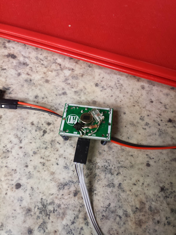
The PIR sensors are pretty standard, but I wanted to jazz them up a bit.  That, and it’s easier to debug if you can see what’s going on.  I was inspired by the ‘electric eye’ description in stories about old-school home automation and added a FET, resistor, and orange LED to light up the shell of the PIR sensor whenever the output is triggered.  Based on my knowledge of historical electronics I would guess that the ‘electric eye’ in those stories is a big freakin cadmium sulfide cell that they pass motor current through.  That being said, tuning one of those systems is no way to have a relaxing weekend if you have a deadline anytime soon.

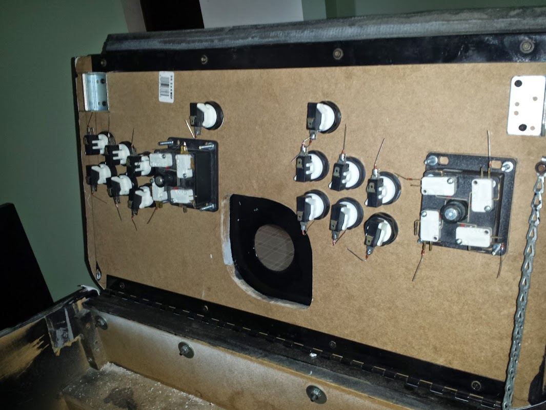
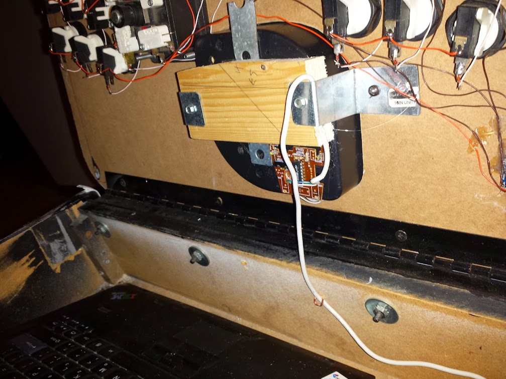
So now we have sensors for people and an actuator for the door.  Now we need limit switches.  My preferred way of detecting the limits of this mechanism is to use limit switches.  You could use motor current, but that is likely to vary over the life of the motor, wire, solder joints, etc. You could implement a rolling boxcar filter to pick out where the current should be based on the assumption it will be changing slowly over time but that relies on good sturdy mechanical connections and not much slop.  It’s also much harder to program, and harder on the wooden gears needing to put stress on the whole system to know when to stop.  The key aspect of using limit switches instead of motor current is that it does not stop if you put your finger in it.  I am of the opinion that if you put your finger in it then you must not care about it enough and deserve what happens to you.  I have also intentionally put my finger in it and with the motor moving on 5 volt power it doesn’t hurt that much.  To address how to fix this (because if the motor does not reach the limit switch then it never stops) I made the code so the iris opens upon reboot.


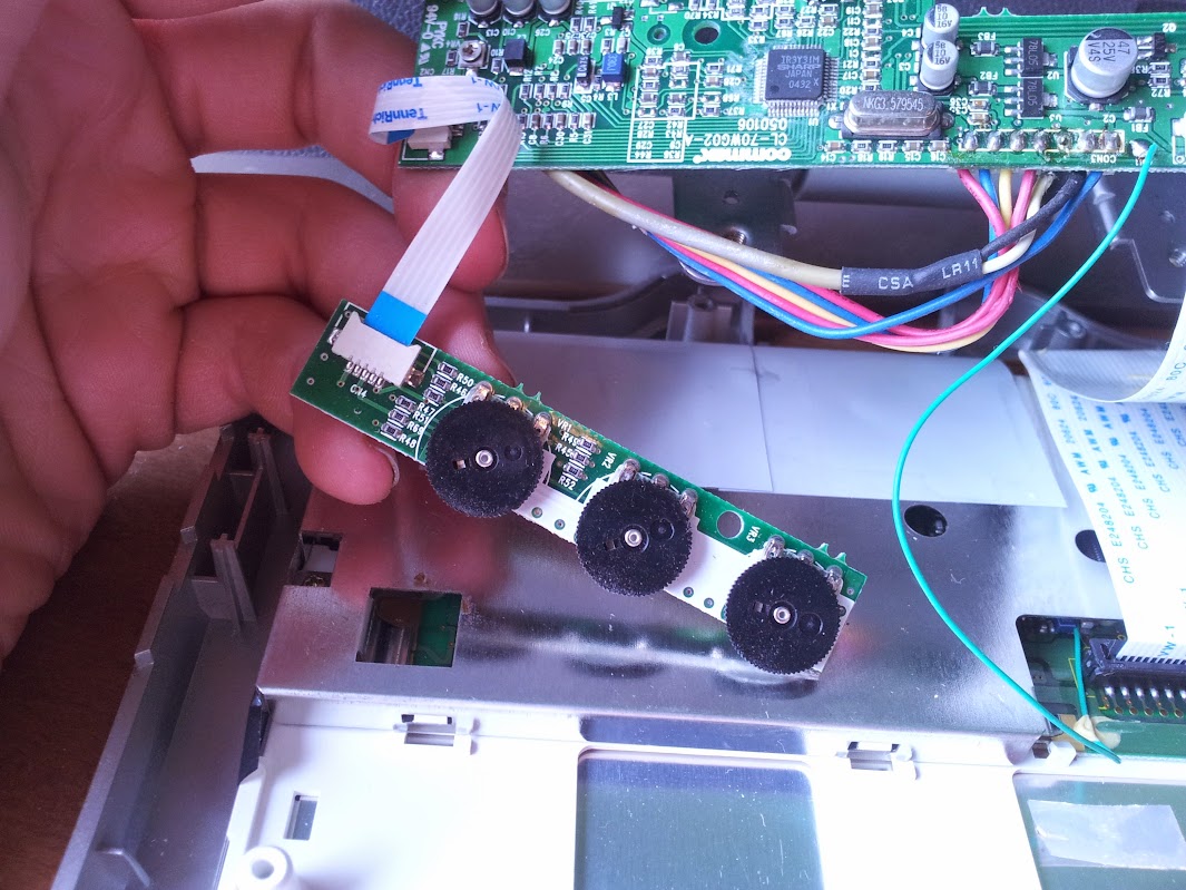
With limit switches you can tell when you’re closed, you can tell when you’re all the way open, but you cannot detect an intermediate state.  This becomes more complicated when you talk about having two limit switches and two triggers on the same gear.  Because of how far the gear rotates to make a full movement of the mechanism it was not convenient to have one magnet and hall effect sensor.  I decided to add 2 sensors and two magnets.  This means that there is one position where the drive gear and ring gear can meet in order for the limit switches to work.  This gets tricky if anyone dis-assembles the mechanism and moves it by hand.

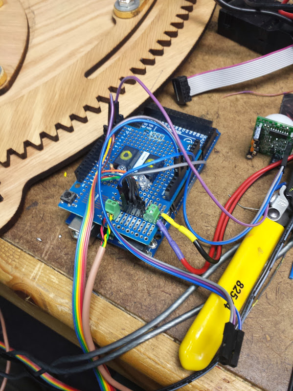
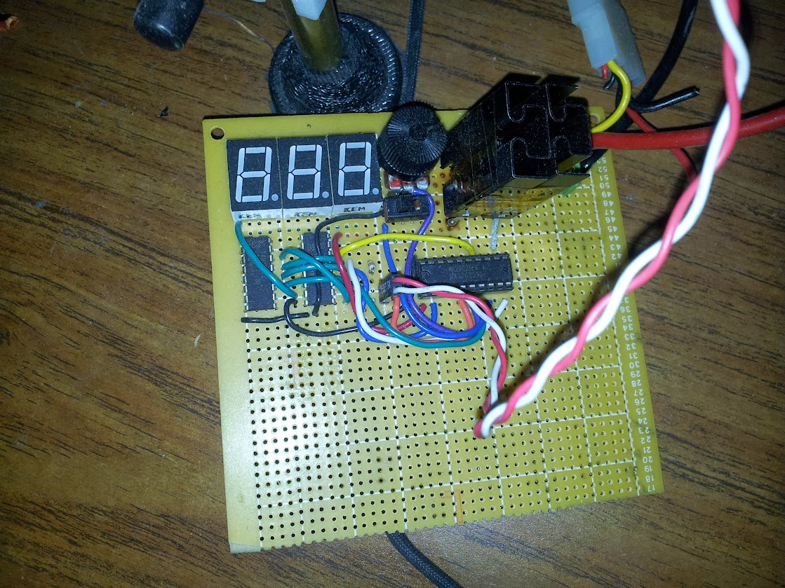
The only remaining question was how to power the motor.  It turns out that the motor that’s designed to run at 12V works great at 5V.  The problem with using a logic and motor power supply together is that when the motor browns out and resets the microcontroller you get a nice infinite loop of opening and closing.  A nice chunky power supply solves that problem.  We switched the motor with relays because the coil current draw isn’t an issue and dissipating the heat a FET would generate is also not how I like to spend a relaxing weekend.

<laser cutter porn>

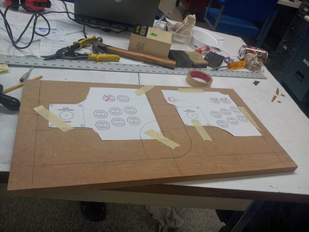
The mechanical assembly was done with chrome 1/4-20 hardware, washers we lasercut out of a single thin sheet of polyester, coconut oiled wood (which we hastily cut on the wrong side, it’s not a symetrical design) and brass flat head wood screws.  The scale was wonderfully coincidental, we were given the porthole which had an ID of 7″.  When we scaled that to the whole project it turns out the 1/4-20 hardware worked great.  The porthole got a lasercut sheet of acrylic to replace the non-existent glass and a translucent ‘i3’ vinyl logo in the center.  The arms that move even got a real gold leaf treatment.  The mechanical build went smoothly and waited for a motor current based control board.  When that didn’t appear I put it into permanent install with my code and limit switches.

The code is supposed to do as follows:

10 open the iris

20 close the iris

30 if either of the sensor lines goes high

40     open the iris

50     stay open until 2 seconds after both sensor lines go low

60     close the iris

70 goto 30

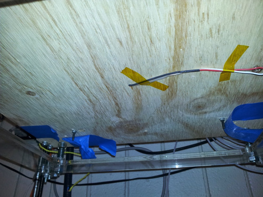
It bounces around a bit and one of the sensor wires has fallen off inside the door (don’t use connectors when you can fit an iron in there, seriously) so it only opens from movement outside.  It’s not perfect, but it’s perfect enough that no one has been motivated to change it in the year and a half since we made it.

pictures and videos here.

code here.

Drill chuck replacement

June 28, 2016

For any of you plagued by modern power tools, I have a reminder for you.  Even if you have to get a drill to finish a project right now and your only option is a speed chuck there is still hope.  Just because you had to buy a new tool doesn’t mean you need to be stuck with crap forever, upgrade it! By using a hammer, a large allen key, and some stiff impacts (don’t burn up the motor trying to do this with the drill) you can remove that new crappy chuck and put on a nice old Jacobs chuck with a key.  Gone are the days of skinning your palms when you try to get a drill bit in and out.  Or the instances when you just can’t get enough torque to keep that hole saw from spinning.  With your newly installed chuck and key you have the needed mechanical advantage that makes a drill worth using.  Ever wonder why not even the cheap companies use a keyed chuck on their larger models? That’s right, you can’t get the needed torque.

Hacked LCD (given composite input)

June 22, 2016

There was a time that I would take any display that I could get my hands on and try to find a composite video signal inside it.  With that information I could modify it to take composite input from my source and I’d have a portable little lcd that I could use with my commodore 64, or raspberry pi, or… game console… this was before the C.H.I.P. or other single board computers with composite became popular.  That technique is still useful today because of the continued prevalence of composite video and the ubiquity of displays that can eat it somewhere inside.

The patient is this audiovox under-cabinet television and radio.  Let’s have a look inside.

My that’s a lot of empty space! if you look closely you can see where a dvd module would go, if this unit had one (!).  I have already hacked this one so there are some things missing.  First, you can see a lack of any RF cans full of tuning equipment, so this can’t pick up video or audio over the air anymore.  I’ll show you a picture of the back soon, but for now look at how sparse the board is (there’s more underneath but look at the unpopulated bits up here first).  There’s a section off to the right that looks to me like a modem.  I don’t know what that was for, really.  If anyone has an idea please let me know because I’m interested.  There’s also a set of unpopulated parts (including what looks like a mains section ) on the left side of the board.  That could be if there wasn’t an off-board power supply, I’m not really sure.  Looking at the parts that are present you can see a long DIP chip with some hefty capacitors, that’s the audio amp.  The connectors just above it in the picture go to the speakers.  The pole of odd stuff at the top of the board is the power supply for the VFD, there’s nothing else that would need those parts on this board.  Let’s rotate.

There’s my hack and you can see where the radio and TV tuner went.  You can also see I didn’t drill those holes, there was an option on this model to come with composite input.  I didn’t try to reverse engineer the extra feature, I just removed the other stuff and used those inputs.  Rotate again.

You can see there’s a bunch more stuff unpopulated, and the section I thought was an unused mains power supply says caution.  Enhance.

Wrong section but I can talk about it anyway.  I find this a little strange, I don’t usually see atmel ICs in the grade of consumer electronics I dissect.  I will point out I could reprogram this to add features and basically do whatever I want.  I would rather… no, this is public and if I use some colorful example someone will use it as evidence to convict me of something.  Let’s just say I won’t be doing that today.  Reposition.

Ok, here’s where I patch in the audio.  I tapped off two pins that I found near the amplifier and I removed the 4051 feeding it so that only our audio is heard.  Reposition again.

Here’s a tricky one, I actually fired up a video game, took a probe, and started injecting composite anywhere on the board I thought likely to work.  I could have probably guessed as well, but this worked really well, especially with no tuner trying to drive the screen black.

This is inside the LCD itself, there was a board to control brightness, contrast, and stuff.  You can see the ribbon that goes between the LCD and the body, I didn’t want to touch that.  So there you have it, that’s how I repurposed a thrift store screen into a portable LCD for use with my raspberry pi.  If I desired there’s plenty of room inside for the pi and a bunch more hardware, the power supply would work well too.  This currently tests composite cameras for my insecure 2.4ghz camera setup that I’m planning around (not inside) my house (post coming soon).

All photos here.

UPDATE 12/19/2022

I finally decided that this is too big and annoying of a form factor to use much. As such I reverse engineered the cable between the screen module and the bigger under-cabinet unit.

I couldn’t find an off-the shelf controller to drive this screen, which is fine because it wouldn’t fit as nicely in this shell. The connector across the top is as follows:

12v, gnd, composite video, unknown, 3v?, IR data, 5v for IR

Interesting thing about this is the only ground wire on that connector is the shield of the cable that carries the video. I wouldn’t have designed it that way… That being said, after hooking up 12v, ground, and composite in I have a working monitor.

I did lose audio, but I think I have a solution for that. The female barrel jack cable I used is actually a barrel jack splitter that I cut one male end off. I fed the unused end back out as a 12v pass-through cable. With this I can design a simple stereo audio amp and power it from that barrel jack. I certainly have some esoteric audio amp chips that warrant a run of 5 specialized boards to use them.

Now, no one point out that the sharp tr3y31m can have rgb in, I’m pretty done with rgb right now.

custom arduino sound board and example

June 22, 2016

So, this is going to get strange if I’m blogging about things I’ve already blogged about.  I’m reaching pretty far back, but I think this is still new to the world.  A while back I designed some boards, which I know is very uncharacteristic of me but I did it and they worked fine.  I was surprised it worked the first time considering I took the schematic for the arduino pro mini, the adafruit wave shield, and a stripped down example circuit for the TPA3116D2DAP.  I’m going to say right now that this audio chip is just silly, especially for my design.  This chip can run in stereo or mono mode, and in mono and properly heatsunk it can drive 100W of power.  I am using it basically at the lowest end of the power curve, at 5 volts where my power supply sits and that puts out about 3 or 4 watts of power.  If I was using about 12 volts it’s be a lot more efficient, but I really don’t care that much about efficiency.  Prototyping that chip was fun, and in the end I looked at the example circuit for the output and figured that since I didn’t stock any inductors they must not be all that important and I omitted them.  Whether or not you agree with the logic, the circuit worked beautifully.  To solder it to a board I put a square of 9 vias and used it as a heat transfer pipe to melt the solder on the power dissipation/ground pad on the bottom of the chip (all you need is a pencil iron, it can solder anything if you’ve got the finesse).

Building your own power amp with these chips is really easy and I highly recommend them in new designs.  Given that my debate was over how to match the power of an lm386 at 9v with a different audio amp at 5v I think I succeeded.  The rest of the board layout went well.  I used a full size SD slot because it’s easier to get full to micro adapters than the other way around.  I broke out all the pins in a square around the package since I didn’t want to bother with the arduino pinout.  The FTDI header is upside down because it was easier to wire that way, there was no provision made for the height of the capacitors but they lay flat just fine, and the switch footprint doesn’t match because I didn’t trust the measurements the manufacturer gave and didn’t have time to get them here to measure myself.  All that being said, the boards worked beautifully the second time.  The first time I found that I got the atmega328 not the atmega328p.  Basically it means that you have to either rewrite the definition to include this fact or run -F in your avrdude command.  I copied the pro mini config file and tweaked one value to create a new board definition.

The wave shield and library are a little… primitive.  Don’t get me wrong, it’s fantastic but it basically hasn’t changed since the arduino was through-hole.  The whole thing relies on just moving chunks of WAV file to the ADC at a regular rate set by the interrupts.  There’s basically no more smarts to it than that.  This means a low part count, very common parts, and editing the library is easy for newbies to coding.

In addition to this  I added a lipo charger (which does not work if you attempt to charge and use it at the same time, from the same source, without diodes) and a lipo fuel gauge.  The fuel gauge may just be a watchdog that monitors the voltage but it’s easier than writing the algorithm myself.  Now I’m up to: arduino, SD input, amplified sound output, battery, charger, monitor.  That’s a pretty self-contained system.  Now on to the tasks I can preform!

The plan was to make the elevator make a sound when moving.  tapping into it wouldn’t be an option because this was actually entered in a hackathon in college and telling them I did that wouldn’t go over well.  I tried discretised integration, I can’t sample fast enough to make an integrator that doesn’t drift.  I thought about using an analog accelerometer and op-amps but I didn’t have any and then I’d be tuning drift with trimpots instead of #defines.  I could also design a completely analog self-zeroing system but I’m lazy and didn’t have the parts at the time.  What I did was implement acceleration bump sensor.  I’d sense a blip either up or down and assume I was in motion for the rest of the time until I felt a bump in the other direction.  This works except I make too many assumptions about how long and intense the bump will be.  There’s play in the elevators I used so jumping on the elevator without it moving is enough to set it off.  I did, however tune it so that with no overly strong exceptions it would work consistently.  I think a gyro would have made this more robust but, say it with me: I didn’t have one at the time.  It’s easy to implement something if you have all the right parts, the challenge is in the hack.

Here’s the video

Here’s the code

Here’s the board

Here’s the pictures


arcade button matrix/control panel

June 22, 2016

I got an arcade machine, but it had a really crappy control panel.  I decided to make a better one (and I did an OK job for a first try).  The first thing was to come up with a template for buttons, joysticks, and my trackball.  I decided how much overhang I wanted on the control panel and how much curve I wanted in the buttons.  I don’t have a process for this, it is a matter of preference.  When laying out the controls think about what games you might want to play.  I hardly ever play fighting games, but I like neo geo very much.  I went with 2×3 buttons because that has a wide usefulness in games and doesn’t look too crowded.  There are still some games that I will only be able to play single player but that’s for reasons like smash tv or robotron 2084.  Once I decided a keep out zone around the edge of the control panel I picked an arbitrary curve for the front.  I could spend forever in CAD making it exactly something, but there isn’t a standard to build to so I just went ahead and laid it out mostly by eye.

Traditional arcade machines use all sorts of materials, but 3/4″ MDF is very common.  It’s eady to get, uniform in consistency, super shitty, flakes like cardstock, soaks water like a sponge, and is heavier than plutonium.  That all being granted, I used it anyway.  After getting some correctly sized hole saws I drilled all the button holes and the holes for the joysticks and trackballs.

oops, those carriage bolts should be under the plexi

The acrylic got a coat of black paint on the underside (so it wouldn’t chip) and so did the MDF (in case it does).  The outside of the control panel has been routed with a 1/16″ slot cutting bit so I could fit it with t-molding.

With all the hardware mounted I installed the buttons and ignored the concept of crimp connectors.  Solder everywhere!  For use with a non-ghosting matrix these buttons heed diodes.  Put simply the matrix can flow current both ways if more than one button is pressed, but these diodes block that so by scanning the matrix I can detect and be sure that every button is pressed at once.

The whole thing is wired together and hooked up to a knock-off arduino micro from ebay.  This is my favorite usb emulating microcontroller, and today it is playing the role of a keyboard thanks to soarer’s firmware as seen in my previous projects.  The matrix config I use is here.

As you can see this was done before I had a laser to cut things exactly.  the right buttons don’t arc like the left, the trackball is off center, and the carriage bolts go through the top sheet.  All in all I’m not a huge fan, but it works.

Arcade Mouse

June 22, 2016

I wanted a trackball on my arcade cabinet, mostly so I could play missile command but I know my mom likes centipede and I’ve always wanted to try marble madness.  Trackballs are common, lots of people put them on arcade machines so it should be cheap and easy to interface with.  Wrong.  Or, somewhat wrong.  This all depends on your level of cheap.  For me I thought the big trackballs were too expensive, and the ones that connect to a computer were even more.  If you think differently just remember this was a few years ago.  If you still think differently pretend it was a long long time ago when my point would be valid even to you.

I came across a trackball on ebay available for purchase.  It was 2.25″ across (boo), about $25 (yay!) and ps/2 (…good enough!).  It had three sets of wires for left right and middle click as well as a ps/2 cable coming out of it.  I have put a picture of it above. If you’ll notice there’s no convenient way to flush-mount this in a wood and acrylic control panel.  My solution involves a 2×4, some brackets, and shims to bring it to the right height.  As imprecise as this method is, I prefer it to a ‘trackball mounting plate’.  Those are ugly.  They also make highball versions that can be mounted like I want to, but they are more expensive.

Over time I came to find that the trackball didn’t work anymore.  I attribute it to me plugging the non-polarized harness in backward and frying the chip on board.  It turns out that all that’s needed these days to make a ps/2 mouse is one monolithic chip, some ir beam break sensors and some buttons.  I reverse engineered it and found that the circuit was as simple as one of these ps/2 mice I got at black friday a long long time ago.  They were $0.50 at abc warehouse so I bought 20 or some stupid number like that, I figured with a fleet of identical ones I could use them in projects… just like this!

Now, I’ve tried before to mod trackballs with a different controller but I wasn’t able to make the new IC like the old sensors so I gave up and stuck an optical mouse sensor under it (and flipped the axes). That led to some skipping because of the mechanical advantage I had over the mouse now that it was a trackball, so I actually prefer this method of modifying it.

I recognize that it’s stupid to hold out for a ps/2 trackball and then replace the controller anyway, but that’s all I had at the time and since it worked I will accept no criticism on it.  I will concede the point that the original PCB is un-needed and I probably could have removed the chip and dead-bugged it, but this was a bit easier and I’m more confident in it.

There you go, no code, no real difficult parts.  If you have an old ball mouse there’s a good chance you can use it as a trackball controller.

standalone heated bed controller

June 21, 2016

Back in the day when I was at college we had a RapMan 3d printer.  Do not buy this printer.  The version we had was flat-pack, made entirely of acrylic sheets sandwiching smooth rods for construction.  Staying up all night to get the first print got us a small ABS plastic cup and a rain of nuts, washers, and bolts.  If you tighten anything down enough to not shake itself apart you shatter the acrylic, and the controller is proprietary, so there’s not much you can do to it from that front.  We spent the first few weeks designing and printing replacement parts for the printer out of ABS because the acrylic was garbage.  The extruders were nice, but used a custom machined razor sharp worm gear that would just chew up material if it was too soft.  On top of all that, it didn’t have a heated bed.  If you’ve ever 3d printed something you’ll know that a heated bed is quite nice and helpful to get good looking parts.  Since we couldn’t interface with the damn proprietary controller we just built a stand-alone one.

We built this in one night, and to my knowledge it never got changed.  This is both a blessing and a curse.  If you half-ass something and it works ‘well enough’ people are not motivated to make a better one, this could mean even more time before you have a reasonable solution to the problem.  If the solution is truly good enough then it’s not an issue, but there’s a spectrum… The other thing worth noting is if someone decided to take a ‘good enough’ solution out of order and replace it with an un-finished ‘right way’ solution taking the functionality from 60% straight down to 0%.  These sorts of ‘fixes’ are the hardest to come back from because it involves either finishing someone else’s project, starting over, or putting back the first solution.  I would tend to lean toward the latter of these options, but that’s not always possible if the parts have been cannibalized in the course of making the whole system non-functional.

Being built in one night it used what we had lying around, in this case an original msp430 launchpad.  These had a bunch of features, plenty of reasons to like them, and most importantly an arduino abstraction layer ported to them.  Arduino may have a bad IDE with very few features and a convoluted system of adding boards and other support, but the important part is that it’s easy enough to get working fast and has enough of a community that making your first few projects work is super easy.  At the time when I documented projects it was on the IEEE Lab Wiki, considering that’s who it was built for and where people would look for documentation on how to use it.  These days I’m going through my google photos looking for something to document, not to bulk out the number of blog entries I have, but just to put together a repository of my knowledge.  I’m not planning on getting hit by a bus soon, but I bought my own house and am already not that healthy of a person.  Here is the excerpt from the wiki article I wrote:

Overview

The heated bed was purchased to increase the quality of 3d prints on the Rap Man. It is constructed from a bed from RepRapDiscount, borosilicate glass from Lulzbot and our own custom controller built from an MSP430g2553.

Specifications

Maximum Build Dimensions

  • X: 214mm (~8.5″)
  • Y: 200mm (~8″)
  • Max Temperature: 110°C (230°F)
  • Power Requirements: 12V @ 8.5A

Design

We wanted to use one of our launchpad MSP430s, but we wanted to do it fast, so rather than learn how to use TI’s IDE (we tried, there were major problems that varied between chips) we used Energia. Using some KEM-5161BR (common anode) 7-segments driven by 2 74HC595N shift registers. To conserve pins we configured the 8th bit on the second shift register to control the third 7-segment as either blank or display a “1”. We have the POT being read on one pin and the thermistor set up as a voltage divider on another pin. The FET (2 in parallel since we needed more current) hooked up to a digital output. The code is [[1]here].

Future Modifications

  • Replace the thermistor table with a function
  • Replace the on/off functionality with a PID controlled PWM
  • Move the FETs to a separate board (or further away from the pot
  • Replace the FETs with one rated for the current
  • Print a PCB


I’m actually not going to elaborate on that because I don’t remember anything else about the design, construction, or functionality. Looking back, my favorite part of the code is the comment “fitted graphically”, I think I’ll use that at work some time as justification for data.  On the subject of ‘future modifications’ I’m pretty sure none of that ever happened, although at least one person got burned by the FET (that really should have been a relay, way higher power with basically no heat).  This article’s ‘value add’ can be my story and perspective on the whole situation I guess.

pictures are hosted here

code (and an unbuilt board design?) is here

original wiki article for the lab is here

ultrasonic adapter for quadcopter

June 20, 2016

This has been in my queue for quite a while (and I’m pushing it out now with no pictures, oh darn).  When I was in college we were working on a quadcopter.  I think our descendants are still working on the same one.  When I was there we had an ardupilot board and were making a frame, tuning the hardware.  One of the optional extras that the ardupilot code can take is an ultrasonic sensor.  The sensor they use outputs an analog voltage.  The sensors I had around used a trigger and echo pin.  Rather than modify the ardupilot code I chose to throw a pro mini at and adapt my sensor to what the ardupilot expects.  Here is my code for how to make a DYP-ME007 act like a Maxbotix ultrasonic sensor.  For anyone who wants to get away with a cheaper ultrasonic sensor here is my code, if it looks simple that’s because it is.

ESP8266 control panel upgrade

June 20, 2016

While writing the article on multiplexing the esp’s inputs I came up with the idea of PWMing all the outputs at once by interrupting the path to ground with an n-FET.  That’s actually not a bad idea, and I have an extra input on the analog MUX that I can use for a light sensor so I can even have auto-dimming.  This is to describe how I did that.

play spot the difference!

With much difficulty and frustration.  That’s how I did it.  If you hadn’t figured it out yet I wrote the intro to this piece before actually preforming the task.  The main problem is that for some reason I couldn’t get input 0 of the analog mux to do anything.  As I think about describing my problem here I also may have the solution… fuck.  The problem is that any input to that input was pulled very very low to the point of pulling more than an amp at a half a volt.  I swapped the chip but it continued to happen.  What I didn’t do was check for a little solder bridge (would have to be very little) to ground which could be what caused the pull down and uselessness of that input.  In order to get around this I added another control line for the mux to use the other inputs.  An act I now realize could have been to move s0 to s2 and tie s0 high so I had to use the other bank of inputs…I was having a good night until I go to write it down, I swear.

So, with a cadmium sulfide cell acting as half a resistor divider I can read the local light level.  That information could be used to dim the LEDs if I had that ability.  It turns out that when I wired the LEDs I tied them all to the same ground wire, one not shared by any other things.  I decided to break the ground wire just before it hit the ground plane and stuck a 2n7000 FET with pull down resistor on it.  This is called “low side drive“, a technique I have paired with individual”high side drive” pins coming from the ‘595.  Since the shift register can only update all of the LEDs at once I decided that PWM through SPI is more convoluted than I want to write code for.  The reason I want dimming is so if I mount this on a wall in a room of my house I can have the LEDs not be obtrusive while still being visible.  That means all I need is to dim them at once so I spend an extra output to control the brightness of all the LEDs at once.

That sums up all the hardware changes I made, if you take a look at the code you will find that I have put in a lot more commands, I have moved some things out to functions, and that I have defined masks for reading/writing bits rather than having hard-coded sequences.  I rather like my new code, but one thing I’m going to move toward is having many topics on each device. The problem with defining the topics now is that if I don’t know where I’m going to put things or how I want them to interact then I can’t design a system.  The problem I face as being not-a-programmer is that I don’t know a good way to parse the payload of a message.  What I have right now is to have a lot of verbatim answers or an’else’ which I use for numbers.  First: I should move to a switch/case structure, and second I could stand to parse a smaller part of the payload making my code more versatile.  I’m not going to do the second one,I will instead move to a lot of topics which contain ‘/’ symbols so it looks like a hierarchy even though it isn’t.

here is the bit of code I updated.

here are the pictures (again).

here is my hub for all things esp8266.

NES/SNES controller adapter

June 19, 2016

Alright, let’s try for one more today.  My queue is finally emptying a bit, it feels like I’m being productive while I’m not actually accomplishing anything new!  This is another post that centers around my arcade machine.  The control panel I have is only two player, this isn’t much of a problem, but I like to solve the general case of the problem.  I decided that for players three and four I would have an expansion box.  Sure, you could use controllers for the other players, but that take re-mapping of the controls for each game and who wants to play with a ps2 controller against someone with a real arcade stick?  My solution, as always, is to use an arduino to emulate a keyboard and this time I decided to make it modular.

This builds off my NES Max mouse, but I expanded the library to read 2 gamepads simultaneously (I apologize for not changing the comments to reflect what I did, but at least I posted the changed code).  The gamepads I chose are the NES Advantage (famously used in ghostbusters 2) and the SNES Advantage (as featured in sentences like “they made an SNES Advantage?”).  The code I used was almost identical to what I used for the mouse except this time I used more buttons.  These controllers have the advantage of having auto-fire capability so maybe people who get stuck with player three or four won’t complain as much any more.

Laser cut box (blah blah) way too big (blah blah) used a teensy 3 (blah what a waste blah).  I think I have to stop blogging, the quality seems to go down throughout the day.

code

pictures


Design a site like this with WordPress.com
Get started