Archive for the ‘projects’ Category

ESP8266 LED Display

September 23, 2015

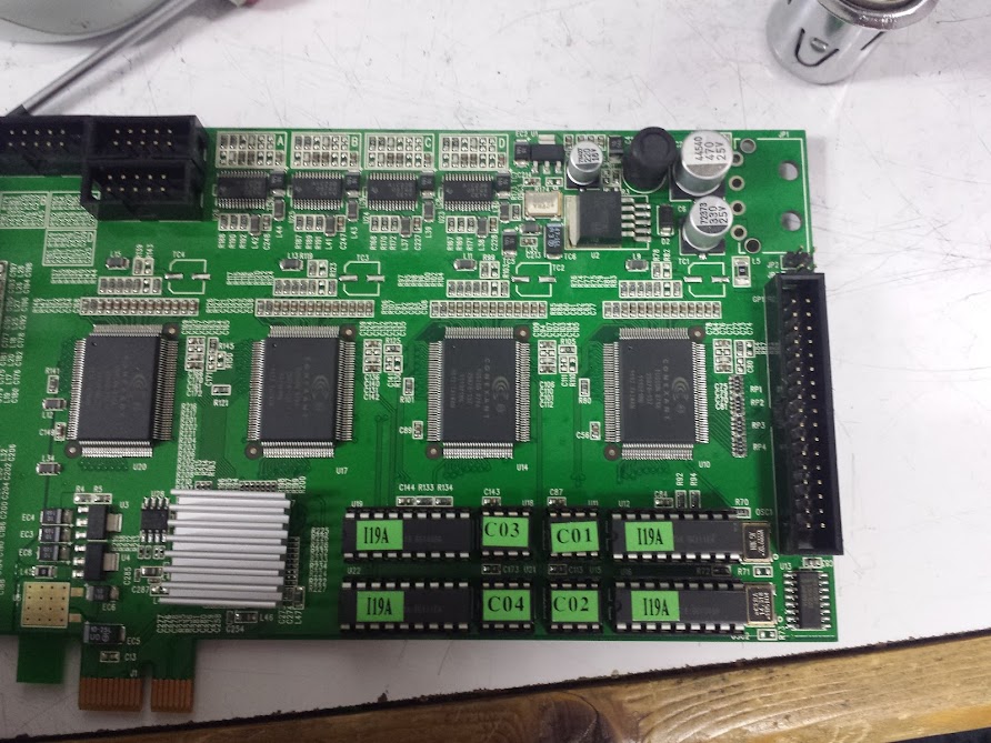
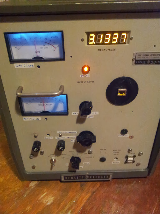
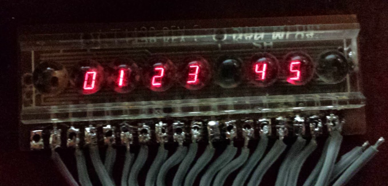
This is my proof-of-concept for using mqtt with the esp8266.  I saw this LED display sitting around and I couldn’t imagine why no one was using it, the answer was no one knew how to talk to it.  Easy, I think.  Looking at the board it’s just an 8031, a serial level shifter, and a bunch of display-centric parts.  The pile of capacitors around the max232 equivalent was the give-away.  capacitors external to the chip are needed in the voltage boosting/negative voltage generation circuits for rs232 levels (until recently, I hear someone put them on-die).  Tracing those signals is easy and I found they went to UART pins on the 8031.

Assuming this chip is just listening for ASCII to be sent to it I started trying all the common baud rates… nothing.  OK, uncommon baud rates… nothing.  Maybe it’s some other parity, or stop bit encoding… nope.  It takes a while to run through all the permutations of rs232, and I did.  Now I’m thinking this takes some special character (or maybe CR/LF) to display a line.  Black-boxing that could be quite difficult.  Somehow, while hammering on the keyboard I saw something.  After trying every character from the ASCII table I came up with this list of printable characters: A-Z, 0-9, space, hyphen.  That’s it.  On a set of sixteen-segment displays.  Even the BOOT MESSAGE has lower case letters! Maybe there’s codes for some things but that’s what I finally gave up on determining.  I’ve settled for that subset of the ASCII set (at 4800, 8N1 if you care).

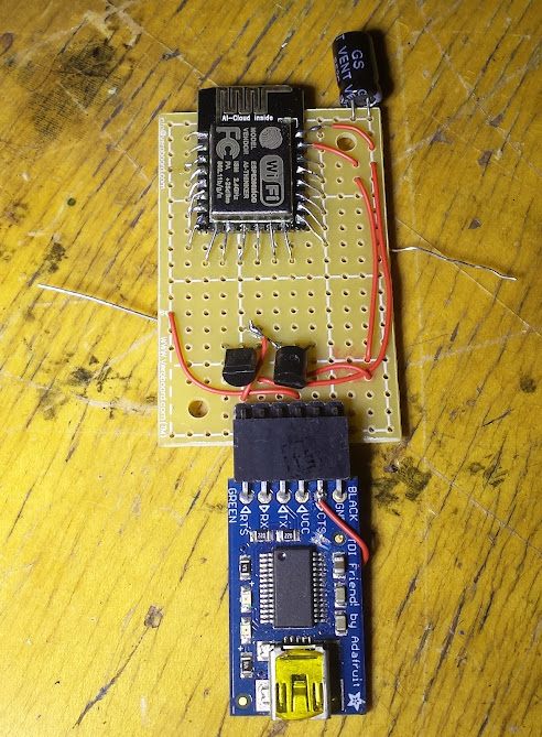
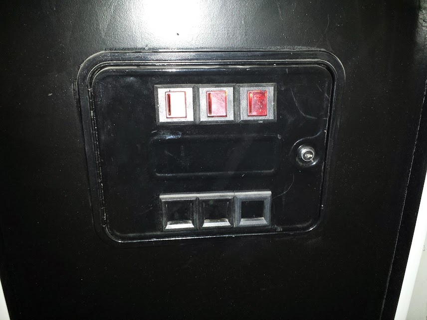
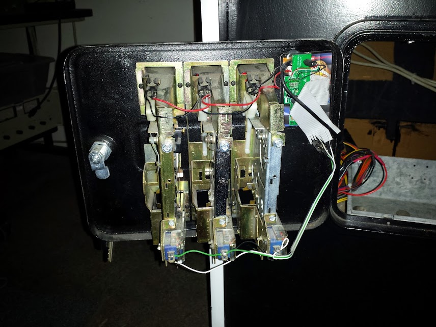
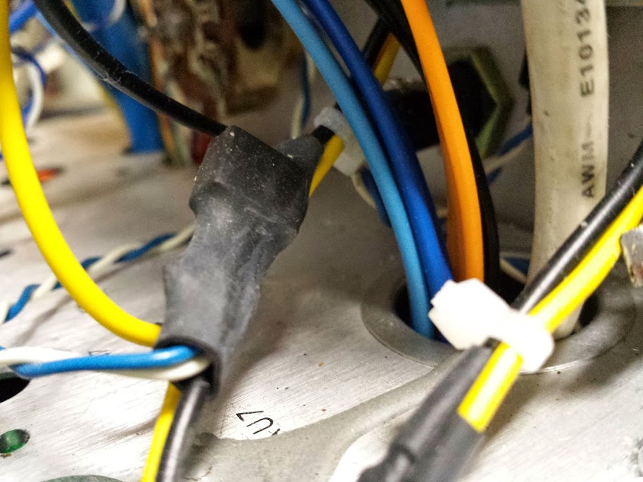
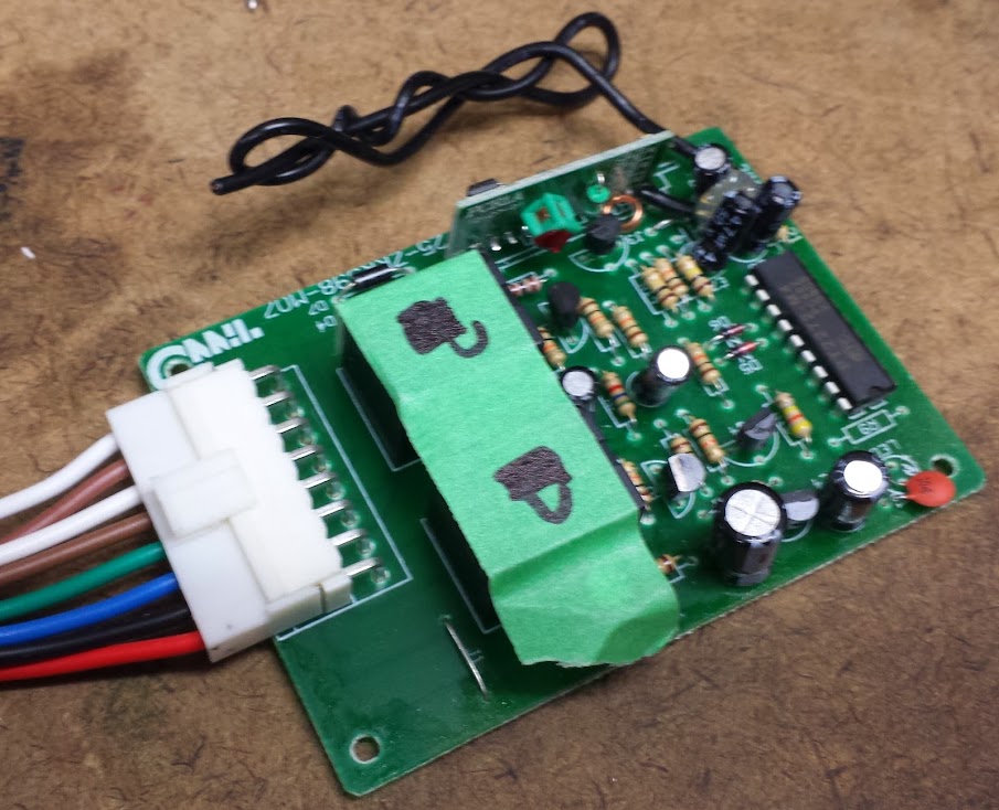
Serial connector added by me

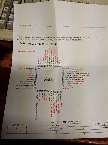
Now we get to interfacing the ESP to this.  Really all I needed was the serial TX pin (actually I could probably use a software serial if it’s just transmitting at 4800 baud and not even listening, but I had a TX pin).  The signals for this sign are RS232 level, not ESP friendly.  I just patched in between the level shifter and the 8031 to get to the 5v level signals, much more microcontroller friendly (if someone says to just flip the polarity and let the rs232 driver at the other end sort it out, just say no!.  Luckily since the ESP only needs to transmit the level converter up to 5v is… nothing! That’s right, sending the 3.3v signal to the 5v chip is just fine.  Probably even in-spec.  Not that it matters since it works.  So now I have a way to talk to this sign from the ESP, but I want to stick it in a box and have it as a completed project unlike most of my hacking which is to write an interface for something and just let it be (never mind that I’m just making this interface to mqtt).

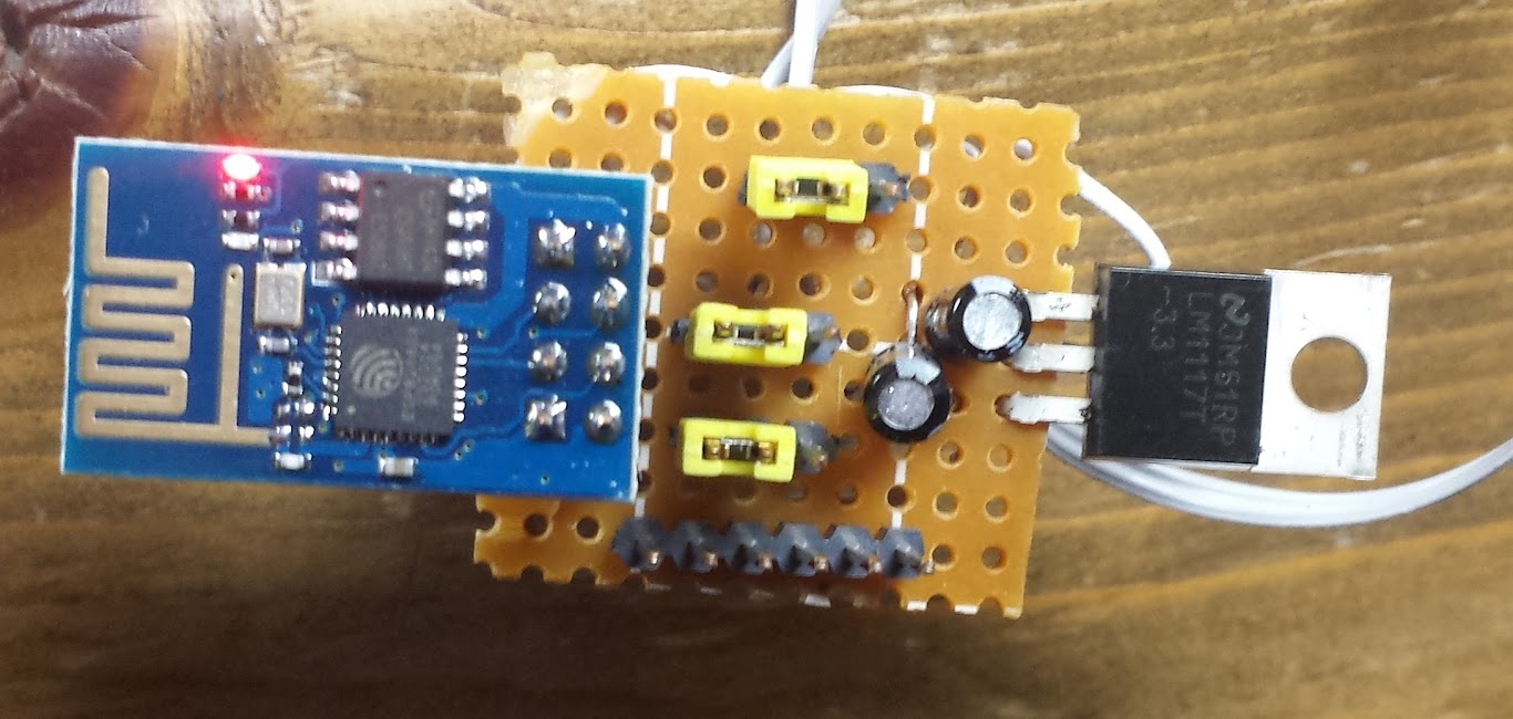
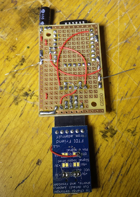
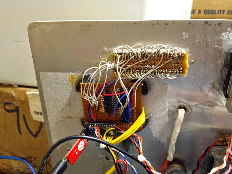
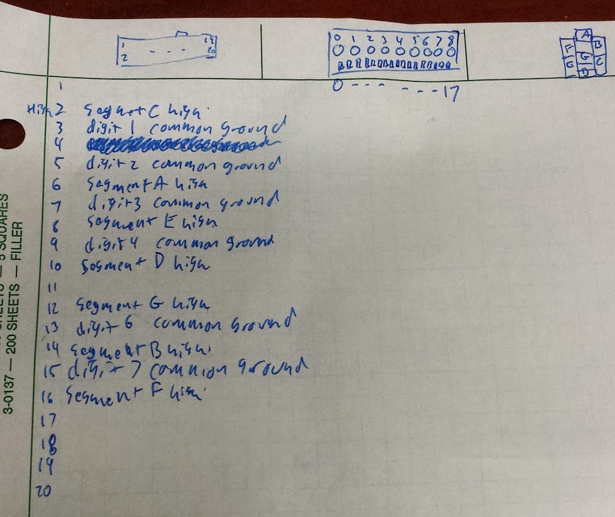
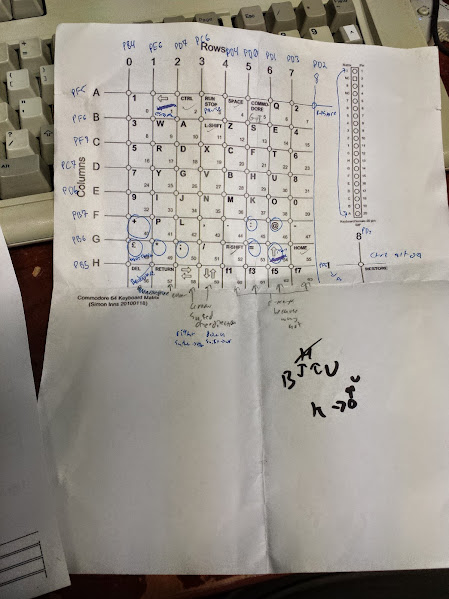
This is what I came up with.  It has an FTDI header, a 3.3v power regulator, and jumpers so I can pick where the signals go.  I don’t feel like typing this out so I’ll add the pictoral documentation (god bless white-board tables).

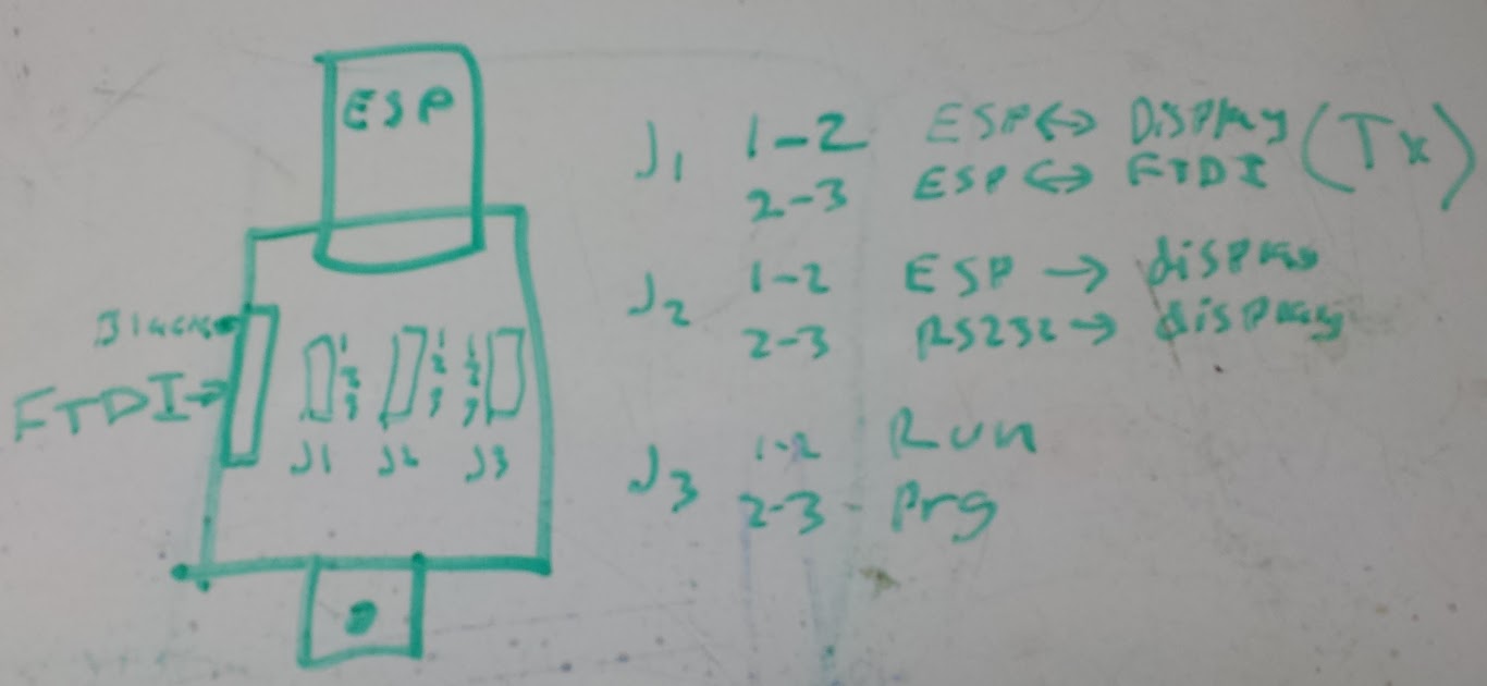
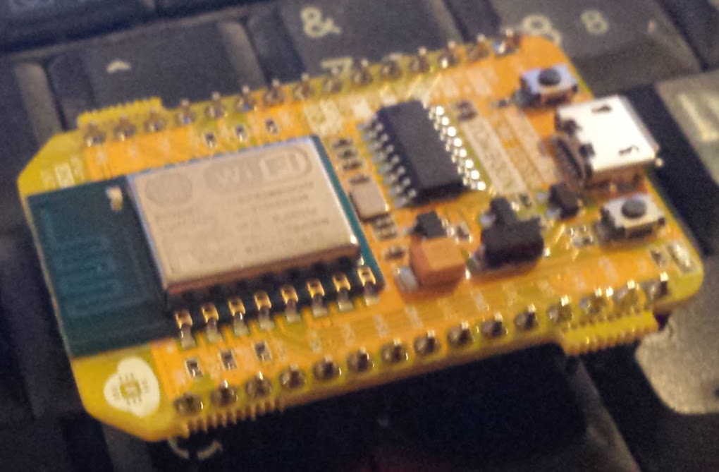
This allows me to set the ESP into program mode, connect the ftdi to the display so I can talk to it over usb directly, or connect the display back through the level shifter to the serial port.  that sounds like enough configuration to me.  Now it needs to go in a box.  Now I’ve got this breakout board soldered to a more edge-friendly one and the pinout looks like this:

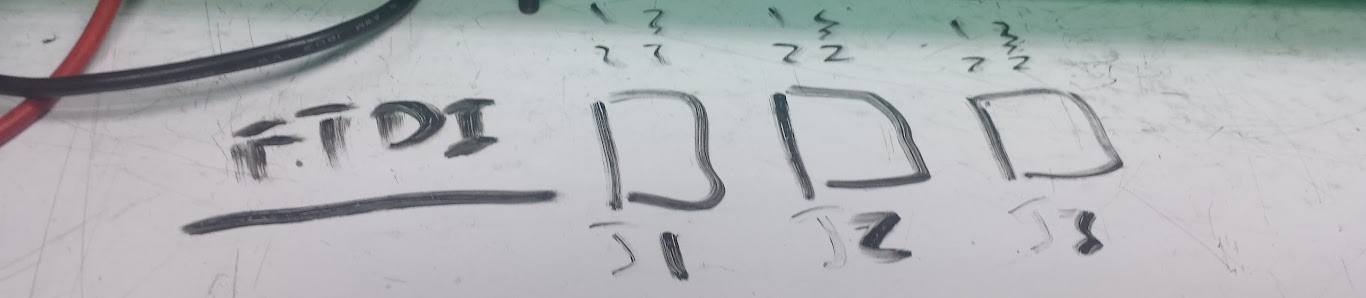
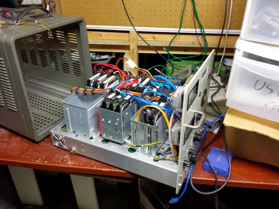
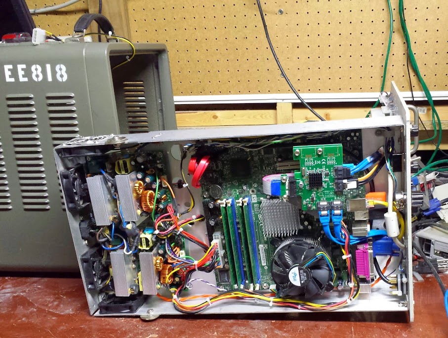
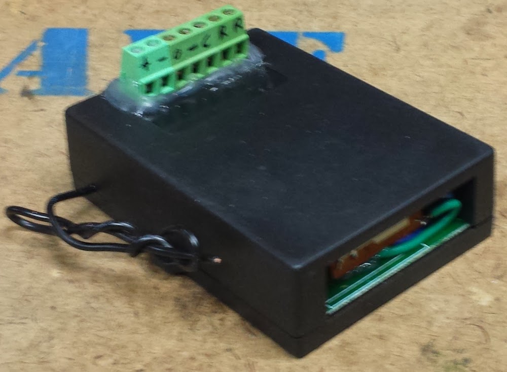
So, along the side of the case I have a barrel jack for power, a DE-9 connector for RS232 level serial, and this layout of jumper positions and FTDI header.  All put together this makes for a pretty decent interface and I have been successful in connecting the FTDI friend (stock one, not my modified one) for programming of the module.  The completed box is transparent acrylic and was made using inkscape, boxmaker, and some custom holes for mounting.

The code for this is fairly simple.  I’m using the PubSubClient library to communicate over mqtt and I use the display for debug since, you know, it’s there.  Connecting the ESP to the wifi means you need an ssid and password (you could implement a clever hopper that looks for unsecured wireless and jumps on that, but I decided that for this I’m not going anywhere and would hardcode the ssid in.  I had it display whether or not it was connected to the wifi, then the IP address it got so I knew it was on (and the right network).  The code then publishes to OutTopic that it has connected (it actually says ‘hello world’ but for now that’s fine, it will change to a unique identifier when I get more of these devices.  It also subscribes to two topics, DisplayTopic and DelayTopic.  Both of those are used for changing the behavior of the sign.  Since this sign takes no input (not even a light level meter) it has no reason other than boot (or perhaps heartbeat) to send any signals out.

The code that handles the scrolling is actually pretty simple.  Since this is updating at 4800 baud the redraw rate is visible, and annoying.  I decided that since every character sent to this pushes the others off the end I’d take advantage of that and just push one character at a time and delay between them to have a given speed for scrolling.  anything sent on DelayTopic will get picked up by this sign and sent through atoi() to convert it to a number.  that number will be the number of milliseconds the program delays for between characters.  Because of this trick I can’t scroll the other way, that would involve redrawing the entire display and it looks terrible.

<Update: the following has been implemented, first try too!> The text interpretation is handled by simply padding with spaces to make the whole message at least 16 characters.  That doesn’t work however since if they are un-displayable the sign does nothing rather than inserting a space so you get smaller strings and artifacts.  The thing to do then is check to see if there is a valid character there and if not put something else there (I wasn’t quite truthful when I said it didn’t display other bits of the ASCII set, it does, but as garbage).  I think in the very near future I’ll put in a check and if the characters are not on the approved list then there will be a garbage character in place instead.

As should be expected the code is here.

The rest of this series can be gotten through from the home page here.

Intro to my ESP8266 adventures

September 23, 2015

Since the Arduino abstraction layer has been ported to the esp8266 I decided to get onboard and start using it for all the networking projects the arduino needs a helper to accomplish.  In short the esp8266 is a little 80Mhz 32bit microprocessor from Espressif that has built in wifi.  It’s a bit of a power hog, but other than needing chunky 3.3v power there’s really not many downsides.  The chip has a very small number of IO for those used to throwing a beagle bone or arduino mega at a problem, but being fast and having SPI or i2c means those can pretty easily be overcome.

esp8266_wide
ESP-01 module (first one people took to)

I’ve been wanting to do some home automation things for a while, and up until now I was adamant that I would run ethernet cables to wherever there needed to be sensors.  After actually trying to run power around my nice, old, heavy, plaster house I’ve found I’m not a fan of plasterwork.  I also found that even the cheapest things you can hook to ethernet are more expensive than one of these esp8266 modules (except maybe one).  There are many of these little modules out there (most using the designation esp-xx) and there are more every day.  All modules use the same chip and bootloader so any dev board could be reprpgrammed to use any code.  This means that when they start showing up in production devices that you can upload your own code to control someone else’s hardware as long as you find what pins go where.

NodeMCU_DEVKIT_1.0
NodeMCU 1.0, my board of choice

There are may ways to program the esp modules.  Lua is surprisingly popular (surprising to me) and done by the NodeMCU people.  Of course the official SDK uses C (there is, sigh, an open source version too).  There is Micro Python for the esp, but it seems very limited at this point.  I use Arduino because the library and community support for it is so easy to access.

I cribbed the part of the circuit from the NodeMCU that makes it not need buttons (resistors on underside)

My favorite (see link below and new article) board to develop on is the NodeMCU 1.0 (or V2) board, it has all the pins broken out, a nice power regulator that you can supply from USB, and a built in usb to serial converter on it.  The other thing they did was use the control lines of the usb-serial chip to hold the lines on the esp high or low as needed to program it.  I liked this behavior so much I copied that part of their schematic to my own board that takes an ftdi friend.  Unfortunately the two control lines it needs are both transmit lines and even adafruit’s ftdi friend doesn’t have solder jumpers for that so I cut a trace and bridged it myself.  My goal was to have something standards compatible and I just ended up inventing my own standard… D’oh.

The push that I needed to get going was from another blog I follow (actually probably from hackaday reposting something he did that prompted me to follow him directly).  He had been using mqtt as a transport protocol to network things together.  I like mqtt for a few reasons, not the least of which it is easy to set up on a pi.  I also like that OpenHAB has a hook for it, but seriously it has hooks for everything so that is probably going to be my main controller.  In the case you need a lot of I/O I would probably SPI/i2c slave an arduino mega and have my own transport protocol for that data (although in practice I usually use the UART SerialCommand library).  There is the ability to do it the other way around, slaving the esp to the arduino and using it as a wifi chip, but now that I’ve seen the esp in action the idea of using clunky AT commands does not appeal to me.

NodeMCU 0.9, not as breadboard friendly

There’s the layout, what my intentions are, and now come the projects.

LED Display (proof of concept)

LED Display (for i3Detroit)

Bistable relay

RTC (set by NTP)

Current sensor

Power node (integrates current reading and relay like the Ubiquiti stuff)

Flow meter (for reading water flow, hot and cold)

Sump Level (probably IR distance and potted in epoxy when done)

Temp and humidity sensor (probably an esp-01 and a dht-22)

Wall control panel v2

PIR motion sensor (same code as condensate pump alarm)

New favorite modules

Setting up a raspberry pi mqtt server to display the IP and hostname on a Nokia LCD

All my code for this stuff will be uploaded here, I already have some of these projects done and will change these listed projects to links once I’ve written the articles.

PV981A-16 mod for autodetection in linux

September 22, 2015

Recently I got my hands on a video capture card, it’s a ProVideo PV981A-16, but I didn’t know that at first.  The card uses 4 Fusion 878a (formerly bt878) PCI video capture cards and a PCI-E to PCI bus chip to give a maximum of 16 ‘simultaneous’ composite video inputs.  In linux there is a driver for the bt878 based cards, and it has quite a lot of options.  These chips were very widely used and the cards they went on had many varied feature sets.  The card has several composite inputs, audio inputs, and some gpio.  The gpio is present because frequently this chip is paired with a TV tuner which requires some digital lines to set the channel or other multiplexers in the audio/video path, or buffered and used for relay contacts or security sensors (like PIR).

Because of the great variety in these cards the driver does its best to autodetect what card is plugged in and set itself up accordingly.  The problem is that the card autodetects as a PV150 (may not be a real card).  When I probed the card I saw 4 chips with 2 inputs each instead of 4, and for quite a while I was scratching my head as to how I could enable the remaining inputs.

trying to use an un-enabled input on one of the tuners

The revelation came that this card was being detected wrong.  Well, not wrong, but the identification the card had was shared (presumably) by another card that only had a total of 8 inputs and it was being detected with those settings.

The ‘right way’ to fix this would be to add a definition in the bttv driver source for my card and have some way to detect it was the right card, but that’s not possible as the unique identifier that each tuner on this card uses is identical to a different card with different settings.  I could have tried to coerce the driver maintainers to accept that enabling more inputs does no harm except there would be virtual inputs with no actual connector for the card that doesn’t use them, but that also seemed hard and not very helpful to the community.  The way to test this would be to remove the driver module and restart it with a manual over-ride that picked a card out of the list that had the right settings.  I found the right settings by poking around in the driver source and finding another card that only differed in how many inputs it had (I knew the other settings worked).  The card I chose was BTTV_BOARD_GRANDTEC_MULTI which is card ID 77, or 0x4d (hex).

This card allowed it to fire right up with the right inputs and all 16 inputs could be detected.  The problem with this solution is that it is not portable.  If you remember from my keyboard adventures I prefer a hardware solution that can be plugged into any computer and work on autodetection rather than a bunch of software fixes that have to be applied after installation.  Looking carefully on the card you will see 4 socketed DIP-8 chips, there are also 2 data lines coming from each and going toward the 878 chips.  I checked and they are each 24c02 i2c eeprom chips, and at the end of their memory they contain hex strings that I recognized from the bttv source code.

This is how these cards are detected (for the most part).  Now I just had to look down the list of card identifiers and over-write these with ones that would detect as the right settings.  The Provideo PV143 seemed to have the right settings (and a similar bit pattern) so I went with it.

My trusty tl866 wrote these easily and now I have a card that autodetects incorrectly (it did before too) but with the right input settings.  I may have been able to just remove the chips and have it autodetect as generic/unknown and had it work, but this seems more resistant to driver autodetection changes in the future.

success!

I did my best to fill out the linuxtv page I linked at the top with all the information I was able to discern from the card (including gpio header pinout)  but it is still not complete.  I have an e-mail out to ProVideo asking for specs but I’m not very hopeful on that front.  After this adventure I feel like I could design one of these cards from scratch, or enable features that were never intended on other cards because they are so simple to use.  Don’t be afraid of the 878, go forth and hack!

arcade coin door

February 8, 2015

This isn’t a big hack, but it’s simple and something that can be done by anyone wanting to convert an arcade machine to MAME.  I started out with a 3-player coin door which is admittedly strange, but the cabinet used to be for Battletoads (a 3 player game).  I spent a long time stripping, cleaning, polishing, painting, and in general restoring this coin door.  Then I moved the cabinet 500 miles to college and 500 miles back.  It is ‘real arcade authentic’ now with it’s distressed look (I got really lazy).

coin door exterior

The coin mechanisms were purchased off of the BYOAC forum and have micro-switches that trigger any time a coin is accepted.  The door was originally lit by incandescent bulbs but I have replaced those with LEDs so I could change their power source (I only had 5 volts to work with).

White LED and resistor in original housing

MAME has a standard set of controls that are applied to all games, these controls default to keypresses on a keyboard.  For example: Player 1-4 start buttons are the number keys 1-4 and pressing 5-8 simulates putting coins into the player 1-4 slots on a real machine.  This list is mirrored here:

Main Keys
5,6,7,8 Insert coin
1,2,3,4 Players 1 – 4 start buttons
9,0 Insert service coin (Needed by some games)
F1 Enables raster special effects in certain games.
F2 Test/Service Switch
F3 Game Reset
F4 Show the game graphics. Use cursor keys to change the set or colour.
F7 Load a saved game state from a slot number.
Shift+F7 Save game state to 1 of 10 slots.
F8 Decrease frame skip during a game.
F9 Increase frame skip during a game.
F10 Speed Throttle (Makes game overspeed)
F11 Frames Per Second and Frameskip information
Left Shift + F11 Enables the profiler in debug versions.
F12 Saves image of game screen to snaps directory.
P Pause the game
Shift + P Skip one frame forward if paused.
Esc Exit from game
“~” or “�” (Above Tab) Volume Control
Tab Access Mame’s in-game menu
Control Keys (Default)
Arrow Keys Controller (Player 1)
Left Ctrl Fire 1 (Player 1)
Left Alt Fire 2 (Player 1)
Space Fire 3 (Player 1)
Left Shift Fire 4 (Player 1)
Z Fire 5 (Player 1)
X Fire 6(Player 1)
R,F,G,D Controller (Player 2)
A Fire 1 (Player 2)
S Fire 2 (Player 2)
Q Fire 3 (Player 2)
W Fire 4 (Player 2)
Not Set By Default Fire 5 (Player 2)
Not Set By Default Fire 6 (Player 2)

The actual interface between the coin slots and the MAME computer is a usb keyboard controller ripped out of a Superman Returns keyboard I got for free after rebate back in the day.  Some people may complain about interfacing with the key matrix and that it creates ‘ghosting’ problems, but this keyboard only needs 3 keys and they’re almost never going to be simultaneous.  The switches are normally open (or I connected them to the normally open contacts) so they simulate keys perfectly.

so hacky

The whole thing is glued to a playing card (I think it’s a lego basketball card) as a nonconductive substrate and glued to the coin door.  You can see I had grander plans for the keyboard controller when I originally freed it from the melted keyboard (don’t leave them in a hot car all summer, they curl nicely).  The matrix was reverse engineered the easy way: by tracing out all the conductive paint on the sheets of plastic with different colored sharpies.

This is a really simple part of the project, now go forth and MAME! having an unfinished MAME cabinet is a rite of passage for all nerds.

——ADDENDUM——-

So, apparently when setting up the software a control key is useful.  I added one switch behind the player 3 coin up, I wired it in parallel with that switch so you can either have a free coin (for player 3) or control the mame backend with it.

Custom file server

September 6, 2014

For the longest time I have been using my main desktop computer as my file server.  This comes mostly from the fact that I never upgraded my computer until enough of it died that it needed a whole new motherboard/CPU/RAM upgrade because I didn’t have any spare parts to revive the old one.  The problem with having a several terabyte file server full of NFS and Samba shared media as a dual boot environment gaming rig is that if I rebooted into Windows then no one (including me) could access the files.  I could have set up the Windows partition to share the drives as well, but Windows doesn’t really like EXT3 or NFS and I don’t like administering windows if I don’t have to.  This resulted in me playing no games (which is arguably not all that bad of an outcome) but I would like the option of playing something and then watching something streamed to my phone or laptop from my server without rebooting.

When Michigan Tech decided to gut and throw out an old HP 612a UHF signal generator I had to jump at it (they also threw out the VHF equivalent, but I hadn’t decided what to do with the one I had yet).  A friend suggested that I build it into a server and I took on the project after making a few measurements.  The bottom of the case where all the passive components and wiring went (remember this thing once held tubes) was just barely tall enough for an intel lga775 stock heatsink to fit, and the power supplies (because of course I had two) would mount just fine if de-cased first.

The case itself had some amenities.  It had a power plug, it had a 115/230 switch, and it had a roll out tray design.  This means that the computer can roll out of the housing while it’s being worked on which makes for great benefit in troubleshooting.  I cut off all the offending steel (not a lot) and added fan holes for the power supply cooling (not terribly well centered).  I got some semi-matched 3-bay 3.5″ cages from scrap computers and mounted them to the main body with brass sandoffs (a friend had a HUGE bag of these).  The holes for the power supply mounting and motherboard mounting are more-or-less standard so when it came time to… upgrade them it went fairly smoothly (upgraded specs mobo/CPU won’t change boot sequence making it’s sata ports useless and old power supplies blew up with PWM-ed load on the 12 volt rails).

that drink might be whisky, I don’t remember..

The computer booted off of one of the cheapest USB flash drives I have ever seen.  This drive had a PLASTIC housing, not a metal one, probably meaning pretty bad sheilding, but it works just fine and is a sandisk so it’s probably ok.  Two USB ports were located to the front panel for ease of interface, the VGA cable is permanently connected, but coiled up inside only to be taken out when troubleshooting.  The network cable is also patched to an external mounted jack, it’s hand-soldered to a board mount jack, so the signal is probably not the best but it’s not a gigabit NIC anyway and I’ve pushed near 100Meg speeds through it.

The two power supplies have their green (power on) and ground (black) wires in parallel, but the rest are floating relative to each other.  This doubles the number of 12 volt and 5 volt rails available however the motherboard is exclusively using one supply.  The cables at the supplies have been de-soldered and I pulled from my extensive collection of Molex and SATA connectors to put together a nice harness for this machine.  The fans are mostly dumb 12 volt computer fans so they are controlled through PWM-ing the power rather than the new ‘4-wire’ fans that have a logic-level PWM input.

The motherboard did not have nearly enough SATA connectors for my taste so I ordered 2 PCI-E 1x 4-port SATA cards and sone PCI-E 1x ribbon cable extenders.  Here is where some people may complain about signal integrity over un-sheilded ribbon, but I will state again that I have had no instability in this server since it was constructed.  The power and reset buttons are on the front panel along with a mains power switch that cuts the power to the supplies killing the whole rig and an ne-2 neon tube that shows the presence of AC power after the switch (tells you if it’s not plugged in or otherwise is without AC).  The fuses for the power supplies have also been run up front.

The custom part of this server that makes it more than just a case mod is in the font panel controller.  There is an arduino pro mini controlling the front panel, acting as a gauge driver and a fan controller.  The fan controller portion is simple, the fan power bus is switched by a big FET pulled from the power section of an old P2-era motherboard and that FET is controlled by the arduino.  The fan speed can be either full on, manually controlled, or temperature controlled.  The temperature comes from a thermistor (salvaged from a power supply) that is biasing a voltage divider read by an analog input.  If set to temperature controlled a PID controller tries to keep the center of the machine below 80F.  This frequently means the fans are always on, but that changes based on where the server is placed for cooling.  The manual control is exactly what it sounds like, an analog voltage read from a potentiometer is converted to a PWM duty cycle.  The mode is controlled by a rotary switch that has various resistors running into one analog pin to minimize pin count (and it was an odd pinout switch).

The big part of the front panel is the meters.  There are two beautiful meters that I have backlit (and the backlight is on an analog voltage control by potentiometer) and a 5 digit 7-segment display meter that fit perfectly where the old wheel didin the front panel.  The digital displat sows exactly what it originally did, ‘Megacycles’.  In this case meaning the current CPU clock speed (which is governed) in Megahertz.  The two analog meters show the RAM and CPU usage and have trimpots on the back to set the scale, well, they’re pots anyway…  Commands are given to the controller over a USB to serial link (knock off FTDI cable) and a python script.  The Script was originally bash with a bit of python because I’m bad at bash math, but it became python with a bit of bash because it’s marginally faster (unless I could run the whole thing in bash).

Because this server is running headless I wanted to make sure it came up and shut down correctly, the way I did this was to make a script that played music using the ‘beep’ command and set it designated on startup, and another on shutdown.  It’s actually fairly easy to get your scripts to launch like any other daemon in linux using this tutorial.

There were a lot of parts for this I modeled in Solidworks and 3d printed because it’s really easy to make LED and button holders that way for oddly shaped holes.  The scripts, arduino code, and solidworks files are on my github here and all the pictures in this post (along with others) are here.

Reverse Engineered Bubble Display

June 15, 2014

I was at hamvention a few weeks ago and ran across some digital stopwatches, the salesman made me an offer I couldn’t refuse so I got all four.  Each had a bubble display inside, but not in a terribly useful configuration.  The displays have nine plastic lenses, but only numbers two, three, four, five, seven, and eight are populated.  that’s a froup of four, a space, then another group of two.  I should also mention that I don’t actually need any more displays, but they always seem so useful that I can’t help myself.  I wrote a generic matrix driver and threw it up on my github here (I swear I’ve written this code a million times, so here it is for general use). The number on the back says “LTB-1467S” T8416 Made in Taiwan, so if anyone else needs this pinout hopefully google will lead them here.

Central locking system conversion to remote power switch (intro to the bistable relay)

June 14, 2014

I a continued effort to re-purpose un-needed items into generic solutions to common problems I have converted this no-name-brand aftermarket central locking system into a remotely switchable power strip.  The system was given to me since the only part of it that was needed for a friend’s hack was the solenoid actuators, with only the transmitter/receiver pair left I thought this would make it at least somewhat useful.

a most generic box


how it originally looked


So, this system used one solenoid and applied voltage one way to lock and another way to unlock.  There are two remotes and the receiver module has spots to wire up buttons for lock and unlock.  The first thing I did was pin it out, the lock and unlock signals are labeled in the above picture.


The inside of it wasn’t too hard to figure out.  Power and found were red and black, 12 volts DC since it was meant for (modern) automotive use.  Brown and white were wired to themselves on the board which left the question as to which was control and which was output.  I checked the bottom of the board and verified with a meter that when actuated to lock blue and green source and sink 12 volts momentarily, and unlock flips the polarity.  Now, the question is how to latch the output so one button closes the circuit and another opens it.

One solution would be to use a flip-flop and set, or reset it depending on the signal.  It might even be beneficial to trace back before the relays to the logic level signals and use those directly.  Then you could simply use the output of the flip-flop to run a fet, SSR, or relay to control your device, but I think I have found not only a simpler solution, but a more efficient one.  You may not think that more relays would make the system any better, but there’s one type that they don’t usually talk about that solves this problem perfectly.

When I was thinking about home automation I wanted to use electronics to flip lights and fans on and off to conserve power, but I had a problem: if I use a relay then it’s always burning power in one of the two positions.  If I hook up a computer in addition to the conventional light switch then either you can turn out the lights, or my sensors or timers can, but then the efficiency gets eaten into by the relay coil burning away the watts silently heating the wall.  I theorized that you could make a relay that is stable in two positions, one that has springs that hold it closed, but coils that pull it to one relaxed state or another.  This would be rather fiddly to build, but it’s not a complex idea.  Another design could use a ratchet to increment along a series of contacts making a kind of electro-mechanical rotary switch.  I really didn’t want to build either of these, but I couldn’t believe they were new ideas.  A trip to google later and I got the term ‘latching relay’ or ‘bistable relay‘ and a couple weeks later ebay delivered me a few to play with.  As an aside, the other design (the multi-pole one) is called a stepping relay.


There are multiple types of latching relay, I chose the type with one coil and flipping the polarity would change the state of the relay (since that’s what the system I had did).  In reality I could have treated both signals individually and used a common ground, but I had this available to me so I used it closer to how it was originally designed.  Now I have a single pole single throw relay contact as an output of an rf remote.  I packaged it all up and the result was this nice neat box.


Now I still didn’t have a use for it in this state, so I threw it in a box, connected it to mains, and have a wireless remote power strip.  I may not have much of a use for that either, but now I can just plug it in and go.

IBM 122 key follow up (2)

May 11, 2014

First post

First follow-up

OK, I finally got around to doing those custom keys.  They’re not the best, but I plan to do it better with what I have learned in the process of putting together this continuing adventure.  Here’s my initial draft of key designs (I’m still looking to put a save key somewhere, not sure where though)

This part was completed at the fabulous i3Detroit hackerspace in Ferndale MI (of which I am currently a member).  Previously I had hoped that I would just be able to mark the keys with the laser cutter, but predictably it just melted and didn’t actually discolor as I had hoped.  I considered using the vinyl cutter to mask and then paint the keys, not fine enough.  I could laser a mask out of something and paint it which I determined to be too much work.  I could also use the laser to cut the keys and wipe paint into it, but all the examples for that show a smooth surface and not only are these keys curved, they’re textured.  The easiest way to do it would be to use the laser to bond a paint to the surface, but I needed a ‘paint’ that would cure to the plastic and I could wash the rest of it away.  Further experiments will be tried using conventional ceramic glaze, but today we had the right tool for the job: Thermark.

Thermark is a fantastic (and fantastically expensive) product that will bond to metal (and plastic as we discovered) with a relatively low power laser.  Our first experiments were preformed on a sheet of polystyrene and apparently wildly out of focus because we were using power levels around 50% and today when I did it we couldn’t go above 30% for raster text.  The first approach was to get the proper font (mostly Helvetica) for the keys and replicate them by rastering across the surface of the key and laying down a beam whenever that pixel should be darkened.  That didn’t work.  It sorta worked, and with much post-processing I’m certain we could make it work, I just don’t want to.

The laser cutter we’re using is the FullSpectrum HL40-5g 40 watt laser cutter and use software called RetinaEngrave.  That software is both fantastic and terrible.  To be honest it may have some of the features I want, but that just pushes it to a UI problem instead of a feature implementation problem.  When you just want to cut something out, or draw a picture into a piece of material it’s fine.  When you want to do fine detail work and have control over the laser for doing extremely fine (and low power) things like this it just doesn’t cut it.  It may not be the computer-side software’s fault however, the controller in the laser cutter isn’t doing it’s job correctly either.

Verticals lost (before cleaning)

Verticals lost (after cleaning)

Some things we learned when making this keyboard: the laser takes time to warm up (and more importantly the controller isn’t compensating).  That means if it’s been off for a second then there is a notable ramp up curve to the power output  of the tube (do more expensive ones just use mirrors and leave the beam on the whole time?).  This became a problem because The vertical lines would only blip on for the shortest time and the laser wouldn’t get up to full power.  If there were any way to raster in the other axis on top of the same design to get a uniform pattern then it’d be fine but RetinaEngrave doesn’t do that.  To fix this we tried slowing down the laser, but that melted the plastic in the parts where the tube was on for an extended period of time.  We tried turning down the power as well but those two never seemed to balance and give us the consistency we wanted.  There was then trying to stretch that axis (theoretically just telling the laser to turn on earlier) but that turned into a slightly bloated interior set of letters (which could be made to work, but I don’t really like that solution: I shouldn’t have to tweak the source material like that to compensate for the tool, I’d rather fix the tool).  Finally we threw out the idea of rastering the font in favor of a nice vector font.

too slow, melted and pooled thermark (before cleaning)

too slow, melted and pooled thermark (after cleaning)

With a vector font we can get a longer beam-on time rather than blips and we can do a fill of the to get any size font we want.  The downside is that I’d have to abandon Helvetica (I’ll be honest, by this point it was Mukti Narrow) for a more common Sans font.  The promises of the Hershey Text from none other than Evil Mad Scientist Laboratories were great in their beautiful blog post about it.  It delivered… sorta… eventually.  First: the version you need is in eggbot_2013_08_11_2.3.4.zip not HersheyText_1.00.zip as it’s a script for the eggbot originally.

tried widening the letters, bled together a bit (before cleaning)

tried widening the letters, bled together a bit (after cleaning)

Once you’ve figured that out then you get to discover that our laser warm up problem has reared it’s ugly head again.  When doing vector letters the first letter of a line would be too light, even the time it takes for the beam to scan back to the beginning of a line on a 12mm wide key has caused it to cool down and not be nearly as dark.  The problem then with noticing it and doing just that key again is that if you only do one pass the tube still won’t have warmed up since it’s still the first letter.  If you run a pass too light then try to make up for it with more passes you’ll run into the distinct non-linearity of the laser power.  The hotspots on an initial light print will balloon out of control to splotches before you get the letter looking dark enough to be done.  The key is the fewest passes to get the job done.

uneven application of thermark (before cleaning)

uneven application of thermark (after cleaning)

You need to actually run two passes over the first letter of each line in addition to running the rest of the cut.  By the end I was doing two passes routinely since it does one cut, then repeats it rather than doing all of the cuts and starting over for another pass.  There is also the concern that we’re not always in the most crisp focus since the keys are curved.  I’m not all that concerned about that  but it could be an alternate reason for the darkening problem (but the verticals problem in the raster letters seems to prove out my theory).  The next time I do this I’m planning on manually editing the Hershey Text created lines to look more ‘Helvetica’.  That being said by the time I got to the last 2/3 of the keys I had a process down.  That process is detailed here:

1) First I traced (all of this in Inkscape) a nice rectilinear picture of a key that had some text in the same position as the text I wanted to mimic (single line, double line, single character, etc…) .  To do this I laid down the snap-lines horizontally and vertically on the top and bottom of the text and the entire key.

2) Then I generated the vector font using Hershey Text.

3) I resized the font (after locking the ratio) to the size of the text on the key I wanted to replicate.

4) I resized (once again, lock those ratios!) the entire outline of a key with text group to be exactly 12mm wide (what I measured the key caps at).

5) Once I had the key the way I wanted it (all vector in this version) I printed it to RetinaEngrave.

6) In RetinaEngrave I disabled the outline (but a perimiter trace still goes around it so I can use that for alignment).

7) I placed the blank keycap (thermark applied with q-tip as evenly as I could manage) on a strip of masonite as a stand (the keycap isn’t level and I didn’t want to build a proper jig just yet).

8) Once aligned I fired a vector engrave with 0.2% power (tube doesn’t seem to come on if the software has it set any lower than that), 80% vector current % (because you can actually go lower) and two passes (to eliminate the dim letter problem).  As far as we can tell the software won’t try to turn on the laser unless power is set to 0.2 or higher, less than that is possible with the vector current % setting, but not much below 50% of that (we used thermal paper as a test bed).

9) Wash with isopropyl alcohol (or honestly probably anything).

As you can see they’re not all straight, or uniformly placed, or uniformly dark… whatever, I’ll try again later.  I personally think the method I have outlined here makes halfway decent keys.  Redo is a raster one, the best we got it, we ran out of keys to test with otherwise it would have gotten the vector treatment too (and New Tab is done over a very light failed stop key (we really ran out)).  A big thanks to Unicomp for still making these keycaps (and blank ones too)!

All the fantastic close up pictures were taken with a Sony a580 digital camera that had a custom adapter designed and 3d printed to fit our Nikon SMZ-2B binocular microscope.  The the 3d model for that will be updated when I get it.  Gallery with more up-close photos is here.  My vector adventures are on git here and I have a post on th vinyl coming up.  

IBM 122 key follow up (1)

April 6, 2014

Continued from here.

I decided to go ahead and order the keys from Unicomp, the quality’s ok, the color sorta matches, but they couldn’t make me custom keys.  I did get a tux key, most of my media keys, a context menu key, and another escape key.  I’m going to apply some inkscape talents to making the key labels, but I’m not sure how to go about marking the keys.  I could mask with tape and burn it off.  I could dust it with toner or thermark and try to melt it in.  I could engrave and try to wipe paint in.  I’m waiting on a part for our little laser cutter, but I’m leaning toward dusting it with laser toner and trying to fuse it into the plastic keys.

Here’s my keyboard a it stands today, I’ll add a picture of my key designs later tonight.

Next post here.

Commodore 64 usb keyboard

April 6, 2014


As I type this the keyboard in my thinkpad t60 is going, so all these keyboard projects are good.  I found that the guy who created the firmware I’m using to interface the ibm 122 key to my computer also developed one that will take a raw matrix and use the same great config file structure to create a usb keyboard.  There are a bunch of options for debouncing, blocking, scanning, and even muxing inputs and outputs to use a matrix larger than the free number of pins on the ’32u4 (or just use the existing hardware in the keyboard).  This project was essentially a proof of concept for my arcade machine keyboard controller so now that this works I can start designing and wiring up the matrix for that.

The first thing I did was get the pinout for the keyboard matrix, then I found that one key is not part of the matrix, so I threw it on one of the rows and made it a new column with undefined keys below it.  Now I have to define a key matrix in the config file, no problem.  I just looked at the documentation, copied an existing config file and went to town.  Some of the keys were in interesting since either the closest key didn’t exist, or I had used it elsewhere I had to use dummy keys.  I chose the “LANG_#” keys since I figured even if one of the keycdes got through the OS would just shrug and forget about it.

The macros I was good at this time around, once I decided what I wanted the keys to do it was just a matter of writing up the commands and bracketing them wit a macroblock.  Enter problem number one, the macroblocks have a fixed length.  I didn’t bother to figure out how many macros could go in one block, I just broke them up into logical blocks and then it worked.

The next one I encountered was that for some reason the PD0 and PD1 pin (arduino D3 and D2) didn’t like being used for scanning.  I don’t know what about them but when I moved to PF1 and PF0 everything went smoother.  For this project I used the olimex-32u4(since the board doesn’t matter, just the mcu) and I decided to cut all the LED jumpers (there are 3) just to be safe.

Now I had a matrix, being read reliably, outputting scancodes more or less properly.  There was still a problem with some keys’ shifted functions not working properly.  I bumped my macro block for the shifted chunk above the general re-maps and that cleared right up.

To sum up the config file: all keys do more-or-less what they say on top.  The odd F-keys are the main buttons, the even ones are done by holding down the commodore key (windows key).  The british pound key is the backslash/pipe key.  My favorite mod was making the “wasd” keys into the arrow keys (since the commodore arrow keys are a mortal sin) using the windows key.

That’ it.  I now have a working commodore 64 keyboard as a usb keyboard.  The project this is for isn’t quite a secret, but despite hackaday’s warning I’m not posting about it just yet.

my config file: here


Design a site like this with WordPress.com
Get started