Archive for the ‘projects’ Category

Saleae Logic clone build

June 11, 2013

So, I wanted a logic analyzer, and I wanted it cheap.  After hearing about the Saleae Logic I was excited, after all what is a logic analyzer but a pile of IO and some nice software.  The thing is, the rate at which you may want to take samples can be much greater than the transfer speed of, say, USB 2.0.  The cool thing about the Saleae Logic, USBEE, Braintechnology USB-LPS, and presumably others is that they use the Cypress FX2 chip.  The main benefit of this chip is that it has an enormous 4 Kilobyte FIFO buffer attached to ports B and D.  That means it can take a huge number of samples really fast.  That chip is really weird, well, it’s the first I’ve heard of having to push firmware to a chip upon plugging it into a computer.  This means that any software that wants to use a peripheral based on this chip can simply push fresh code on boot to the processor, allowing firmware upgrades to be as easy as software upgrades for the client software.  This also means that any software is free to push it’s code to any peripheral and try to use it.  This could be problematic if you end up trying to output into a one-way buffer chip or anything else since the associated hardware could differ wildly from devices utilizing this chip.  The way around this is to have an I2C EEPROM that has the usb Vid:Pid on it, allowing authentication of peripherals to the software.  This method can pragmatically be used for protection, or used for DRM (I think you see where this is going).

overview with crappy cable

There is an open source logic analyzer project known as sigrok that has a client for many different logic analyzers, and a sub-project fx2lafw which is a firmware for FX2 based logic analyzers.  They have a wealth of information about various logic analyzers, especially the FX2 variants.  Some of the stuff I found most interesting was the details on which eeprom and buffer each device uses. Since I am planning on using this chip as a logic analyzer, and as such will be connecting it to foreign/unknown hardware I think an input buffer is pretty important.  I went with the ST DVIULC6-4SC6 because that’s what the Saleae used, it’s fantastically simple, it’s just a diode array used to tie any over voltages to the power rails, so you just tap it right on to your data lines, not through.  The benefit of these is that they’re designed for ESD and can respond even with signals switching at up to 1.65Gb/s.  Now the other thing the sigrok site has for input protection is series resistor values.  Clamping diodes protect from voltage, but series resistors protect from current.  While they don’t actually list the resistor values, they have detailed pictures with which you can actually read the smd markings… except the Saleae uses packages without markings <sigh> whatever, I used 4.7k 603 package ones between 2 pads on a standard perf board.

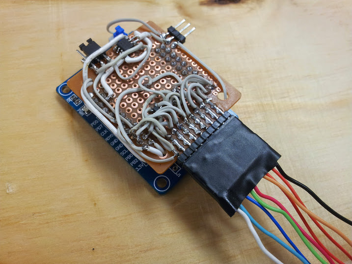
close up of my hackery

My original plan was to break out all 16 pins of the FIFO (prots B and D) so that I could have a 16 channel logic analyzer, but ST only samples one of each part and only had 2 variants of the ESD chip, so… I’ll do that later if I really want it.  Now I just needed to figure out the EEPROM problem.  I bought the Lcsoft CY7C68013A Mini Board off of ebay for ~$15 it comes with an EEPROM on it and a jumper to set the address of the chip, the problem is the chinese company used an EEPROM with 16bit memory addressing and put it at the address where the Saleae looks for an EEPROM, except the FX2 needs an EEPROM with 8bit addressing at that address, and the Saleae won’t look at the address where the FX2 will allow a 16bit addressed EEPROM.  Basically, while they tried to create a knock off, they failed.  I know they tried to create a knock off because I dumped the 24c128 they had on the board, it had the right USB Vid:Pid on it for the Saleae.  Well, it’s fantastically easy to find EEPROMs of the required interface as they are used all the time as the DDC chip in any VESA compatible display (VGA, DVI, or HDMI ports each have one) to communicate to the computer what resolutions a monitor is capable of.  There is a way to use the Cypress tools to reprogram the EEPROM if you don’t have any other tools to do it, but I just used my tl866cs, fantastic programmer (trying to upgrade it to a tl866a).  I salvaged a few from the logic board of a long dead and smashed LCD, wrote them with the required bytes and voila! we have a Saleae Logic.  but that’s not enough, oh no, I need to make this better than retail.  How about making it also a USBEE ZX? well, kinda.  I have yet to figure out what pins on the FX2 map to the Trigger and Clock on the USBEE ZX.  Also, I have some sources that say the USBEE ZX is not as picky about the EEPROM type as the Saleae is.  And I needed to solder a jumper from the board to the protoboard since 5v isn’t broken out on the headers (for the GND, 3.3v, 5v header).  So, I grabbed another EEPROM, burned in some new Vid:Pid bytes and hey! it works too!

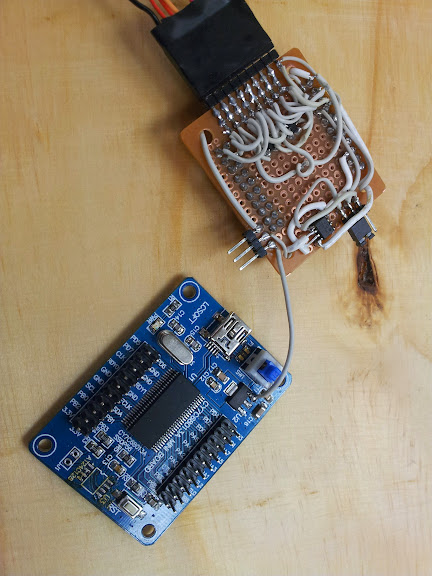
yeah, I soldered a wire, boo hoo

Fabrication took place in my signature style: using whatever I had lying around and not bothering to etch a board.  Don’t get me wrong, I can etch a board in a few hours with the tools at hand, I just didn’t feel like it.  “But they’re surface mount chips” I hear you cry.  “But I don’t care” I respond.  Some people invest in rework stations and reflow ovens, all I need is a really, really fine tip on my iron.  Not for this project though, a regular fat tip will do just fine.  “How can you solder those chips down? the pin pitch isn’t right”.  Ok, fine, scrape off 2 circles of copper and straddle it with the EEPROMs tack the corners and the 2 center pins on each side aren’t soldered to the board.  “But you have 2 EEPROMs…”.  Do I even have to say this one? Stack them, wire all pins in parallel except the SDA line, switch that one with the jumper.  “Ok, fine, but the SOT23-6 don’t stradle like that, ha!” Ok, fine, shave off half a pad, straddle the middle pin over that space.  “Hey, you should get some 30 gauge kynar wire for that, works great”.  I’d love some… oh, you’re not offering? well then, scrap 40pin IDE cable it is.  Some fantastically cheap 0.1″ female headers from ebay (not breakaway, but at these prices I can sacrifice a pin every time I want to shorten them), scrap male headers from an old motherboard, and a jumper from a dead IDE CD drive, and a bit of nearly new protoboard, now I’ve got a logic analyzer.

Features:

8 channel logic analyzer + ground pin

jumper to select which EEPROM

in line resistor protection

diode clamp protection

GND, 3.3v, 5v header (on the USBEE)

power button

Things I missed/messed up:

USBEE trigger and clock pins

ground pin should be on other side (to match Saleae)?

PORT D (remaining 8 pins for use with sigrok)

References:

’C0-A9-08-05-00-84-23-00′. this is the VID:08A9 and PID:0005 for the USBee ZX device. ‘C0-25-09-81-38-1B-00-00’. This is the VID:0925 and PID:3881 for the Saleae device.

PORT B[0:7] => Saleae[purple:black] (I think that’s the correct order)

Links:

list of FX2 devices in sigrok

my board

what I’m trying to emulate

the other one I’m trying to emulate

original inspiration (gave me the EEPROM info in the comments)

gave me the Vid:Pid

lots of useful info, just not essential to my project

how to write the EEPROM if you don’t have any other way

Easy Computer Power Switch

August 23, 2011

I can’t seem to find my inspiration for this (I blatantly ripped off someone else’s project) but I thought I’d post it.  I work on lots of old computers, and frequently when I’m testing a whole lot of motherboards I find it useful to have this header made out of a bit of pcb, a panel mount db9 connector shroud, and  an old pc switch harness.  There is no circuitry, nothing complicated or even innovative in this project, it’s compact and I find it useful.  (photos courtesy of my HTC dream [G1], new camera on the way)

Remote Control Switch

July 28, 2011

Over this summer I have been to some decent garage sales, although my subdivision’s garage sale has been moved to September (when I will be about 500 miles away at Michigan Tech).  One of the things I usually think about when deciding to purchase items is ‘how does it work?’.  This is probably pretty common among makers and hardware hackers, but it has always been a sticking point for me because I rarely want to use a device for it’s intended purpose.  One of the things that caught my eye was an old radio shack remote controlled coax A – B switch.  In my experience consumer electronics from this era (don’t get all pedantic on me, I can’t tell you a year, but in my experience things from a certain era have similar external properties, construction techniques, and internal properties) are constructed internally in a nice, easy to understand manner that operate how I would expect.  For example They tend to do things like use a linear voltage regulator to step the voltage down to what the chips require, rather than a convoluted set of diodes in series and resistors that are carefully selected to allow the exact voltage and amperage that the circuit requires.

Once open I found what I had assumed there to be, a voltage regulator, a couple of ICs whose datasheets were readily available, and a relay that is either switched on or let relax to form the two switch positions.  An interesting thing I found is that the reason this device is rated to work at 12 volts is that the relay is actuated by a transistor that directly switches the unregulated input on and off.  If you were to replace the power supply with one of any voltage from 7 to whatever voltage the 7805 can take you could replace the relay to match that (assuming the transistor that switched it could take it as well).  While I was trying to pin out the existing relay I eventually gave up and replaced it with a 12 volt relay I already had on hand.

I then ran that to a speaker cable spring clip thing that came off of an old amp some time ago, thus making it A Com Com B.  I set it up so when the light for A is on the red connector on the A side of the device was connected to common and vice versa.  I have no normally open and normally closed, I have A, B, and common.

This design could do with a latching relay so the coil does not have to be drawing power the entire time one of the two settings is actuated.  That, however is another project I would like to try which is a three way switch (or an n-way switch) that is just a button that switches the current position of the switch regardless of the current position.

The pictures that would allow you to build the entire device from scratch (re-construct the schematic from the board layout) are available at this link: https://picasaweb.google.com/Abzman2000/RemoteControlSwitch?authuser=0&feat=directlink

Razer Barracuda HP-1 Gaming Headphones mic build

July 15, 2011

Recently my local area was subjected to what I hear is called a ‘100 year rain’ it is apparently a rain so hard (for a given area) that a storm of it’s magnitude only happens once every 100 years (once again, it is for a given area and what constitutes a 100 year rain would vary from area to area).  My house was not hit terribly hard, the roof leaked in one room which may have destroyed some not-so-valuble crap in my attic that we have now taken as an oppurtunity to pitch said crap, the basement flooded a tiny bit since sometime in the past the sump pump had failed and we hadn’t noticed (this is a whole other story), but certain areas of Livonia had the basements flood entirely.  By entirely I mean there was at least a foot or two of water in the basement, there is some controversy about whether or not the city had the opportunity to direct the storm drains into the freeway to prevent t from happening, whether it was truly a sewage backup, and plenty else that basically sums in up as the city not taking responsibility for their sewer system not being able to handle a ‘100 year rain’ (as I see it they know it will flood once a century and have no plan for that).

I guess that was my small rant for today, I can’t really feel too invested in someone else’s fight against the city since the only way it affects me is that I have some slightly damaged cool new stuff and I helped haul some seriously damaged heavy stuff out of a friend’s basement.  Moving on to the relevant topic for which this blog post is titled, one of the things this friend gave me while I was helping him clear out his basement was a pair of Razer Barracuda HP-1 Gaming Headphones.

Ovierview shot

My Glorious New Headphones

Since the headset I was using up until now was a 2.5mm mono headset from an old RadioShack telephone this was quite an improvement, but there were two problems: one, the left side was not working, and two, there was no mic.  let’s start with the seemingly difficult part, repairing the left side.  Now, recently I have decided to write a book (or probably it will be a wiki), A long time friend of mine mentioned that we would do something ‘by the book’ when I started to describe some of the mundane details of how I proposed we go about doing something, and after that I proposed we write a book of how we go about doing things.  From generic troubleshooting to favorite torrent sites and programs we use all the time, we would create a manual usable by people who are not us to do things the way we would.  It would kinda be a collective skill set that we have acquired over the years, the main thing that would be at the top of all the lists is ‘Try Re-Seating ALL Connectors!’.  It turns out that these headphones are meant for the Razer Barracuda AC-1 Gaming Sound Card, and it uses a DVI connector to pass all it’s 5.1 analog sound and 5. power to the amp.

the connector

That Damned Connector

Going off an another considerably shorter rant, I fully support the use of existing connector styles for tasks completely different from their original intent as long as they can not reasonably be confused with the connector’s new purpose.  Meaning I support the use of the DVI connector on this audio card and these headphones since I find it unreasonable for someone to mistake a pair of headphones for a monitor (also, there’s a key in the connector, a missing pin on the female connector preventing you from plugging a monitor into your sound card and potentially damaging in if they chose to put the 5v on a pin that might damage the monitor).  I do not support someone making a device that outputs 12v on a usb style connector (since they are commonly used for charging devices at 5v).  The key in the connector means that without a modification to the cable one would not be able to use a standard DVI cable to act as an extender for the headphones (not that you need to since they are so long).  The headphones have a small breakout adapter that puts all the audio inputs on to 3.5mm connectors and a usb one for power (the graphics cord comes with a similar adapter that turns it into 3.5mm female jacks).

the breakout cable

Said Breakout Cable

Getting back to topics at hand, all I had to do was plug the connector back together (it was not screwed together).  The real thing I actually did to these headphones was building a mic for them.  I cracked open the earphone of the headset using the three phillips head screws located just under the foam of the ear piece, once open it was fairly easy to read the pcb and figure out what the mic pinout had to be.

mic jack pcb

The mic Jack pcb (more detailed photos in the album)

I don’t know what the original headset did to light up the leds around the jack, but without internal modification to the headset I could not figure out how to light up them.  The tip of the 3.5mm phono connector is mic+, the ring in mic gnd, and the shield is the negative side of the leds that has to be grounded for them to light up, but when I connected the shield and ring together the leds did not go on, it was not until I connected mic gnd to the gnd pin on the leds on the side that the leds on the bottom lit up.

new gnd wire

New gnd Wire

I don’t know where the mic itself came from, it was in one of my parts bins with a very long cord on it, and a stiff wire for the last couple inches of the wire.  I chose it for that purpose exactly, I used the stiff wire to hold up the mic, I fastened it to the ring and shield of the 3.5mm connector.

new mic jack

I documented the disassembly process as well as I could and have it posted to my public google photos for anyone else who might find it useful.

https://picasaweb.google.com/Abzman2000/RazerHeadphones?authuser=0&feat=directlink

Repairing Rock Band Drums

July 6, 2011

Continuing in my trivial repair series I bring you the drums.  One day (about a month ago) I was out driving around at night through my friend’s neighborhood the day before trash day when we come upon something interesting.  It turned out to be an xbox 360 set of rock band drums, complete except one of the far pads was completely broken off.  After I got it home it was trivial to replace the broken wire with another one (a twisted pair from a bit of ethernet cable) however the hardware repair proved to be a bit harder.  My normal approach is to use hot-melt glue or fiberglass resin to just put it back together, but with the forces that would be torquing the joint would shear off any adhesive quite quickly.  What I decided was that I needed was a rigid piece of material to bridge the gap and I needed to permanently affix the new material to the existing body.  For the material to act as a bandage I used some bits of a computer case (one drive bay cover and two strips cut from the case of a power supply) and for the adhesive I used pop rivets, they are cheap, fast, and easier than a nut and bolt.  Since the cable didn’t come with a USB connector on the end I ended up using a female USB b port salvaged from an old printer, insulated with some medical tape since we were out of electrical tape (we now have five rolls since I got fed up with not having any and went out to get some today).

Bottom Brace


Back Brace

Front Brace


USB Connection

I promise my posts will get more substantial as time goes by, trying to archive my own minor fixes I do on a regular basis (I do have some actual mods and hacks coming up soon).

Repairing Rock Band Guitar

July 3, 2011

Recently I went to visit a friend living in Mt Pleasant and while I was there he gave me this guitar that he said was his housemate’s, and it was broken.  Well, being me I naturally assumed that I could fix it no problem, and I was right.  Upon close inspection one of the 90° .1″ headers had all three pins broken off.  Not having a three pin 90° .1″ header I used what I had, in this case a 3 pin .1″ header salvaged from an old broken motherboard (probably a header for either a turbo button or a cmos reset jumper).  All I did was solder the header to the remaining pins to make a 90° header.  I have pictures of the entire board to document the orientation each connector has to be in for it to work properly.

in all it's glory

The Patient

opened for all the world to see

The Guts

not perfect, but it'll do

The Opperation

Oh, in addition to that the whammy bar had the spring broken off, I assume this is why it was dis-assembled in the first place, then the header got broken while it was open, and I fixed that by bending a little more of the spring into a loop and re-attaching it.

Zune: Followup

June 20, 2009

I really anticipated it would have taken me a longer time to get around to doing this, but was given some opportunities, and actually got it done, here’s how it went.  As soon as I posted my last blog post I went out to a coffee shop where one of my friends worked.  I picked up someone on the way, we call him British, and I knew he had a zune (and is probably one of my 3 readers at this point) so I had him bring his charging cable along.  Now I never really expected to have the thing power up on the first try, but I was really hoping it would (it did not).

We’ll skip ahead in the night to after I got home (~4 am), I was strangely motivated to try and take the thing apart, but didn’t want to ruin it.  I went out in search of websites with disassembly guides and found one as the first result of my first search (I have mad google-fu skills).  The guide (seen here) says to use one of those plastic safety tools as to not mar the surface of your pod, but I don’t have one (nor will I get one to disassemble a free zune) so I used what I had, a $0.99 aco hardware box cutter.  I used this tool without fear because the 30GB zune has a surprisingly large gap in it’s main body construction so it was easy to work the long flat dell edge of the knife in there and pop it open (I may do a video, but not at this time).

So, after getting it open I layed it all out, as seen in these pictures (camera phone, I will replace them when I can find my better camera).

Photobucket
Photobucket
Photobucket
Photobucket
Photobucket

It’s kinda hard to see, but the main board has corrosion all down the right side. I plan to try rubbing alcohol on it to see if I can clean it up, and if I’m extremely lucky, make it work again. If I can not I may try to obtain a zune that is broken is some other way (with a working main board) for really cheap, or if all else fails I have repair parts for another common consumer electronic device (I love to have repair parts) and an amazingly small 30GB 1.8″ ZIF hard drive (MK3008GAL) to do whatever with (maybe increase internal storage of my EEE 701?).


ADDENDUM: shortly after this I gave the device to a friend who said he could fix it (I knew he couldn’t) and I ended up giving up parts that could have gone to fix a different friend’s zune.  You can see where I come down on doing that again.

Zune: New Project

June 20, 2009

So, my first blog post just happens to be my first new project since starting a blog.  There are many more un-finished and un-started projects to post on, but listing them all right now would waste my time and yours, so I’ll start with this one: free broken zune.  that’s a phrase I’ll probably be saying a lot, “free broken X”.  This zune is a white 30GB model that won’t power on.  The previous owners said that one day they let it run down too much and then it just wouldn’t re-charge.  I plan on trying several different strategies to repair this zune.

First: I plan to borrow a friend’s charging cable to see if it’s something as simple as that (although I don’t think so, because I’m pretty sure they had a boom box dock for it that would keep it charged while it played)  or at least continuity check the cable with a pinout of the zune side connector.

Second: I would remove the case and battery and attempt to power the zune with a battery pack of my own design (probably a bad idea, but as a test I don’t think it’ll kill it).

Third: try and re-solder the zune connector if broken off the board or bypass it with a hardwired usb cable to see if that’s the problem.

Fourth: buy a new battery from an aftermarket seller (maybe dealextreme or ebay).

Fifth: at least I can probably rip a working 30 GB drive out of this thing, or maybe sell it on craigslist, or maybe both…. maybe not.

Any way I slice it  come out on top because I got a free zune, usb cable, and wall outlet usb adapter.


Design a site like this with WordPress.com
Get started